




Air is supplied to the engine cylinders through the air filter, carburetor and intake pipe.
The exhaust gases are released into the atmosphere through the exhaust manifold, the inlet pipe, the additional and main mufflers.
Fuel tank
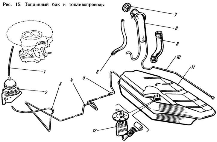
Stamped, welded, consists of two stamped steel half-cases. The tank is connected to the atmosphere by a ventilation hose 10. The filler pipe 8 is connected by a hose 9 to the tank branch pipe, and is closed at the top with a blind screw plug 7. A fuel level sensor 12 is installed on top of the tank.
Fuel pump
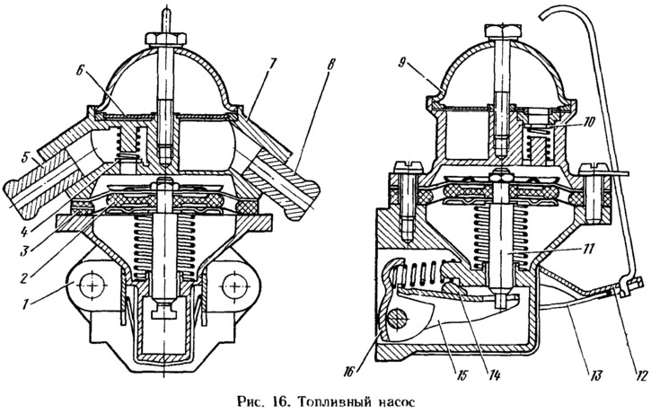
Diaphragm type, mechanically driven, equipped with a lever 12 (figure 16) manual pumping. The pump consists of a lower casing 1 with drive levers, an upper casing 7 with valves and pipes, a diaphragm unit and a cover 9. Three diaphragms are installed between casings 7 and 1: two upper working ones for fuel supply, the lower one is a safety diaphragm to prevent fuel from entering the drive casing if the working diaphragms are damaged. Between the diaphragms there are outer 3 and inner 2 spacer gaskets. The outer gasket has an opening for fuel to escape if the working diaphragms are damaged. The diaphragms with plates are installed on the rod 11 and secured from above with a nut. On the rod under the diaphragm unit there is a compressed spring. The rod with an L-shaped tailpiece is inserted into the slot of the balancer 15 and allows, without disassembling, to remove the diaphragm unit. Levers 12, 16 and balancer 15 are installed in the lower housing. Above the balancer there is a cam 14 of the lever 12 of manual pumping, pressed by a spring 13. Inlet 10 and outlet 4 valves are installed in the upper housing 7. Cover 9 is attached to the pump housing from above with a central bolt. Between the cover and the housing there is a plastic mesh filter 6. The upper housing has a discharge 5 and suction 8 branch pipes.
Information copied from the portal VAZbook
Air filter
Dry type filter with replaceable filter element. The filter housing is installed on the carburetor, sealed with a rubber gasket and secured with three brackets to the cylinder head cover studs and the carburetor bracket. The filter element is interchangeable with the filter element of the VAZ-2121 engine, made of special cardboard with a pre-cleaner. A valve is installed in the inlet pipe of the filter housing, the position of which is fixed by a spring.
Carburetor
Models 1111-1107010 and 11113-1107010, emulsion type, two-chamber, with falling flow, with sequential opening of throttle valves (figure 17). The carburetor has a balanced float chamber and a crankcase gas extraction system behind the throttle valve.
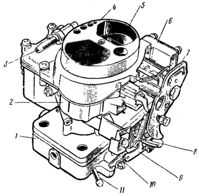
Figure 17. Carburetor 1111-1107016: 1 - throttle body; 2 — carburetor body; 3 — fuel supply pipe. 4 — carburetor cover; 5 - air damper, 6 - starting device; 7 — air damper control lever; 8 - return spring; 9 — second chamber throttle valve drive lever: 10 — second chamber throttle valve lever; 11 — pipe for supplying crankcase gases to the throttle space of the carburetor.
The carburetor has two main metering systems, a transition system and an idle system with an electromagnetic shut-off valve of the first chamber, a transition system of the second chamber, an economizer, an energy economizer, a diaphragm accelerator pump, and a starting device.
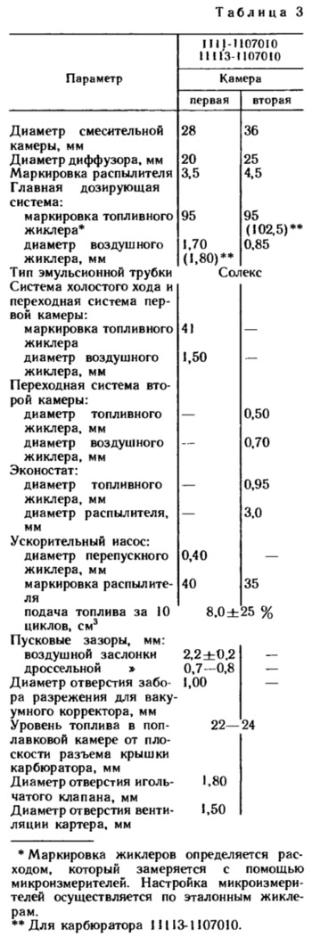
Carburetors 1111-1107010 and 11113-1107010 differ from each other only in some calibration data. The main data of the carburetors are given in Table 3.
The main metering system is fed from the float chamber, into which fuel enters through the needle valve 22 (figure 18). Through the main fuel jets 25 and 40, the fuel enters the emulsion wells. At sufficient vacuums in the sprayers 9 and 16 of the main metering systems, the fuel mixes in the emulsion wells with the air entering through the main air jets 8 and 17, and is sucked into the diffusers of the mixing chambers in the form of an emulsion. In throttling modes, only the main metering system of the first chamber operates. The second chamber begins to open and operate when the throttle valve 34 of the first chamber opens more than two-thirds.
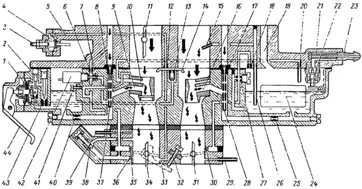
Figure 18. Operation diagram of the carburetor 1111-1107010: 1 - accelerator pump diaphragm; 2 — accelerator pump check valve plug; 3 - starting device adjustment screw; 4 - diaphragm of the starting device; 5 — air channel of the starting device; 6 - idle air jet; 7 — idle fuel jet; 8 - main air jet of the first chamber; 9 — sprayer of the main dosing system of the first chamber; 10 — inertial economizer atomizer; 11 — air damper; 12 — starting device air jet; 13 — accelerator pump spray valve; 14 - accelerator pump nozzles; 15 — economizer nozzle; 16 — sprayer of the main dosing system of the second chamber; 17 - main air jet of the second chamber; 18 — air jet of the transition system of the second chamber; 19 — float chamber balancing channel; 20— tube with fuel jet of inertial economizer; 21 - fuel filter; 22 - needle valve; 23 — fuel supply pipe; 24 - float; 25 — main fuel jet of the second chamber; 28 — tube with fuel jet of economizer; 27 — fuel jet of the transition system of the second chamber; 28 - emulsion tube of the second chamber; 29 — branch pipe for suction of crankcase gases into the throttle space; 30 — outlet openings of the transition system of the second chamber; 31 — second chamber throttle valve; 32 — idle mixture quantity adjusting screw; 33 — first chamber throttle lever; 34 — first chamber throttle valve; 35 — outlet openings of the first chamber transition system; 36 — idle system outlet; 37 - emulsion tube of the first chamber; 38 — adjusting screw for idle mixture quality (composition); 39 — vacuum intake pipe of the ignition advance vacuum regulator; 40 — main fuel jet of the first chamber; 41 — additional air adjustment screw for factory idle speed system adjustment; 42 - Shut-off electromagnetic valve; 43 — accelerator pump bypass jet; 44 — accelerator pump drive lever.
The idle system provides the required composition of the combustible mixture at idle. In this case, throttle valves 34 and 31 are closed. Fuel from the emulsion well of the main metering system of the first chamber rises along the fuel channel, passes fuel jet 7, mixes with air from air jet 6 and enters as an emulsion through outlet opening 36 into the throttle space. Air is additionally sucked in from the mixing chamber under screw 38 of the mixture quality.
The transition system of the first chamber ensures a smooth transition of the engine operation from idle to throttle modes. At the moment of the beginning of the opening of the throttle valve 34 of the first chamber, the outlet openings 35 fall under vacuum, from which the emulsion will also flow, ensuring smooth transitions.
When the ignition is turned off, the electromagnetic shut-off valve 42 is turned off, the needle closes the fuel jet 7 and does not allow the engine to operate with the ignition off.
The transition system of the second chamber ensures a smooth transition of the engine operation at the moment of the beginning of the opening of the throttle valve 31 of the second chamber. At this moment, the outlet openings 30 fall under vacuum, the fuel from the float chamber rises up along the fuel channel, passes the fuel jet 27, mixes with air from the air jet 18 and in the form of an emulsion along the emulsion channel enters through the outlet openings 30 under the throttle valve.
The econostat enriches the combustible mixture with fully open throttle valves at speeds close to maximum. With open throttle valves, the vacuum in the mixing chambers and sprayer 15 of the econostat increases significantly. Fuel from the float chamber enters through the jet 26 of the econostat, rises up the tube and is sucked into the mixing chamber through the sprayer 15.
The inertial economizer prevents the fuel mixture from becoming lean during a sharp left turn of the car, when the fuel in the float chamber mixes to the right and the fuel level above the main fuel jets 25 and 40 drops significantly. During a sharp left turn, the fuel in the carburetor shifts to the right and floods the tube 20 with the fuel jet. The fuel will flow through the fuel channel through the atomizer 10 into the mixing chamber.
The accelerator pump is of the diaphragm type, driven by a cam on the axis of the first chamber throttle valve. When the throttle valve is opened sharply, the cam presses the lever 44 and through the spring in the pusher acts on the diaphragm 1, overcoming the resistance of the return spring. The diaphragm feeds fuel through the channel through the ball valve and injects it through the sprayers 14 into the mixing chambers of the carburetor. During the return stroke of the diaphragm, under the action of the return spring, fuel is sucked from the float chamber through the check ball valve and the bypass jet 43 into the working cavity of the accelerator pump.
The starting device ensures the preparation of a rich combustible mixture when starting a cold engine. When turning the lever 8 (figure 19) clockwise, the throttle valve 9 of the first chamber is slightly opened by the outer edge a for the adjusting screw 10. At the same time, the expanding groove between the inner profiles b and c of the lever 8 releases the pin of the lever 3 of the air damper and it will be held completely closed due to the return spring 1. The axis of the air damper 2 is offset, therefore the air damper after starting the engine can be slightly opened by the air flow, stretching the spring 1, which ensures the leaner mixture.
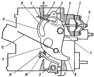
Figure 19. Carburetor starting device 1111-1107010: 1 - air damper return spring; 2 - air damper; 3 — air damper lever; 4 — diaphragm rod; 5 - diaphragm; 6 - adjusting screw; 7 — air damper control lever axis; 8 — air damper control lever; 9 — first chamber throttle valve; 10 — adjusting screw for opening the throttle valve of the first chamber; 11 — first chamber throttle lever; 12 — air damper drive handle rod; a — edge of lever 8 to provide starting clearance of the throttle valve of the first chamber; b — the upper profile of the groove of the lever 8, providing mechanical opening of the air damper; in — lower profile of the groove of the lever 8 for limiting the maximum opening of the air damper; B — starting gap at the air damper; C — starting gap at the throttle valve of the first chamber.
The vacuum from the throttle space acts on the diaphragm 5 and can slightly open the air damper by means of the rod 4. The adjusting screw 6 allows you to regulate the amount of damper opening.