
Models 2105-1107010 and 2107-1107010 carburetors (pic. 40) emulsion type, two-chamber, with a falling stream. They have a balanced float chamber, main dosing systems (pic. 41), enrichment device (econostat), idle system (pic. 42), transition system, diaphragm accelerator pump, positive idle economizer, diaphragm starter, crankcase exhaust spool valve, second chamber throttle pneumatic actuator (pic. 43).
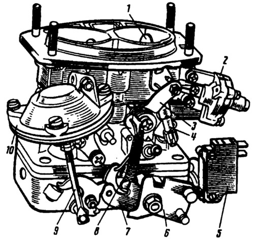
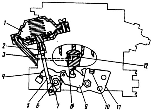
Pic. 40. Carburetor models 2105-1107010 and 2107-1107010 from the throttle actuator side:
1 - air damper; 2 - starting device; 3 - three-arm air damper control lever; 4 - telescopic rod; 5 - microswitch; b - throttle actuator lever; 7 - lever limiting the opening of the throttle valve of the second chamber; 8 - return spring; 9 - pneumatic actuator rod; 10 - pneumatic actuator of the throttle valve of the second chamber.
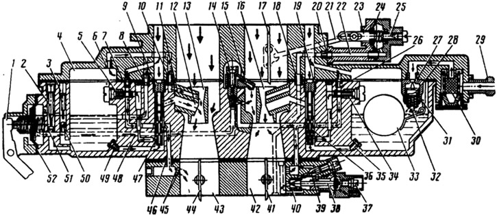
Pic. 41. Scheme of operation of the carburetor models 2105-1107010 and 2107-1107010:
1 - accelerator pump lever; 2 - adjusting screw of the accelerator pump; 3 - cork; 4 - float chamber; 5 - housing of the fuel jet of the transition system; 6 - econostat air jet; 7 - air jet of the transition system; 8 - econostat fuel jet; 9 - main air jet of the second chamber; 10 - emulsion jet econostat; 11 - econostat atomizer; 12 - atomizer of the main dosing system of the second chamber; 13 - small diffuser of the second chamber; 14 - screw valve of the accelerator pump; 15 - accelerator pump sprayer; 16 - small diffuser of the first chamber; 17 - air damper; 18 - adapter sleeve; 19 - main air jet of the first chamber; 20 - jet starting device; 21 - thrust of the drive of the starting device; 22 - air channel of the starting device; 23 - stock; 24 - aperture of the starting device; 25 - adjusting screw of the starting device; 26 - idle air jet; 27 - needle valve seat; 28 - needle valve; 29 - fuel supply pipe; 30 - fuel filter; 31 - float bracket with stop; 32 - damper ball; 33 - float; 34 - idle fuel jet; 35 - main fuel jet of the first chamber; 36 - emulsion tube of the first chamber; 37 - adjusting screw for the amount of the mixture; 38 - forced idle economizer needle; 39 - quality adjustment screw (composition) mixtures; 40 - economizer needle seat; 41 - throttle valve of the first chamber; 42 - first mixing chamber; 43 - second mixing chamber; 44 - second throttle valve; 45 - unregulated openings of the transition system; 46 - adapter sleeve; 47 - emulsion tube of the second chamber; 48 - fuel channel of the accelerator pump; 49 - main fuel jet of the second chamber; 50 - check valve of the accelerator pump; 51 - bypass jet of the accelerator pump; 52 - accelerator pump diaphragm.
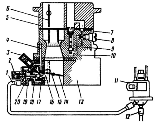
Pic. 42. Wiring diagram for forced idle economizer pneumatic valve:
1 - hose connecting the economizer with the pneumatic valve; 2 - adjusting screw for the amount of the mixture; 3 - quality adjusting screw (composition) mixtures; 4 - emulsion channel; 5 - carburetor cover; 6 - air damper; 7 - air jet of the idle system; 8 - housing of the idle fuel jet; 9 - fuel channel; 10 - emulsion well; 11 - economizer pneumatic valve; 12 - hose going to the intake pipe; 13 - throttle body; 14 - throttle valve; 15 - openings of transient modes; 16 - outlet of the idle system; 17 - air supply channel; 18 - economizer needle; 19 - economizer housing; 20 - economizer cover.
Pic. 43. Scheme of the throttle valve drive of carburetors 2105-1107010 and 2107-1107010:
1 - the cavity of the pneumatic actuator above the diaphragm; 2 - stem bushing; 3 - air channel for supplying vacuum to the pneumatic actuator; 4 - throttle control lever of the second chamber; 5 - pneumatic drive rod; 6 - axis of the throttle valve of the second chamber; 7 - lever connected to lever 4 through a spring; 8 - pneumatic drive jet located in the diffuser of the second chamber; 9 - lever limiting the opening of the throttle valve of the second chamber; 10 - lever rigidly mounted on the axis of the throttle valve of the first chamber; I - throttle actuator lever; 12 - pneumatic drive jet located in the diffuser of the first chamber.
Models 21051-1107010 and 21053-1107010 carburetors began to be put on cars from 1985-1987. Carburettors are structurally different from those described above and are installed on engines: 21051-1107010 with a cylinder displacement of 1.2 and 1.3 liters, 21053-1107010 with a displacement of 1.45 liters. Between themselves, carburetors differ only in calibration data.
Models 21051-1107010 and 21053-1107010 carburetors emulsion, two-chamber, with a falling flow, with sequential forced opening of throttle valves (pic. 44). The carburetor has a balanced float chamber, a crankcase exhaust system for the throttle valve, heating of the throttle valve of the first chamber at the emulsion outlet from the idle system. A manually operated air damper is installed in the second neck of the carburetor cover above the first chamber.
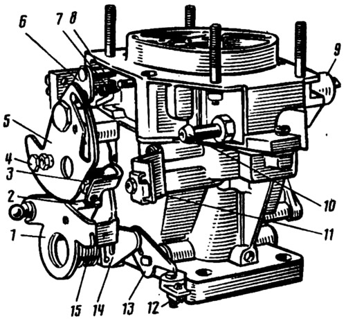
Pic. 44. Carburetor models 21051-1107010 and 21053-1107010 from the throttle actuator side:
1 - throttle control lever; 2 - pin of the lock lever of the second chamber; 3 - adjusting screw for slightly opening the throttle valve of the first chamber; 4 - screw for fastening the air damper drive rod; 5 - air damper control lever; o - air damper lever; 7 - air damper return spring; 8 - diaphragm rod of the starting device; 9 - electromagnetic shut-off valve; 10 - fuel supply pipe; 11 - bracket for fastening the shell rod; 12 - adjusting screw of the second chamber; 13 - throttle lever of the second chamber; 14 - throttle actuator lever of the second chamber; 15 - return spring.
There are two main dosing systems in the carburetor (pic. 45), transition system and idling system of the first chamber with an electromagnetic shut-off valve, transition system of the second chamber, power modes economizer, diaphragm accelerator pump, starting device.
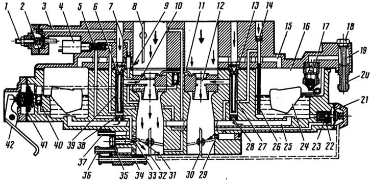
Pic. 45. Device carburetor models 21051-1107010 and 21053-1107010:
1 - adjusting screw of the starting device; 2 - diaphragm of the starting device; 3 - air channel of the starting device; 4 - electromagnetic shut-off valve; 5 - idle fuel jet; 6 - main air jet of the first chamber; 7 - idle air jet; 8 - air damper; 9 - idle flow channel; 10 - atomizer of the main dosing system of the first chamber; 11 - accelerator pump sprayer; 12 - atomizer of the main dosing system of the second chamber; 13 - main air jet of the second chamber; 14 - air jet of the transition system of the second chamber; 15 - float chamber balancing channel; 16 - float chamber; 17 - needle valve; 18 - cork; 19 - fuel filter; 20 - fuel supply pipe; 21 - diaphragm economizer power modes; 22 - fuel jet economizer power modes; 23 - ball valve of the economizer of power modes; 24 - float; 25 - fuel channel; 26 - fuel jet of the transition system of the second chamber with a tube; 27 - emulsion tube of the second chamber; 28 - main fuel jet of the second chamber; 29 - outlet openings of the transition system of the second chamber; 30 - throttle valve of the second chamber; 31 - slot of the transition system of the first chamber; 32 - throttle valve of the first chamber; 33 - outlet of the idle system; 34 - carburetor heating block; 35 - quality adjusting screw (composition) idle mixtures; 36 - branch pipe for suction of crankcase gases; 37 - pipe for supplying vacuum to the vacuum ignition controller; 38 - main fuel jet of the first chamber; 39 - emulsion tube of the first chamber; 40 - ball valve of the accelerator pump; 41 - accelerator pump diaphragm; 42 - accelerator pump drive lever.
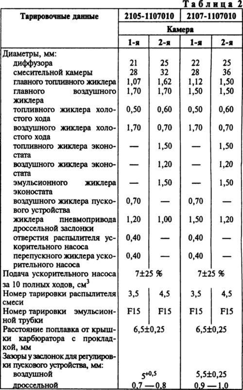
Calibration data for carburetors are given in table. 3.
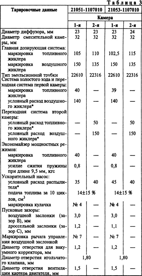
* The conditional consumption of the jet is determined by the reference jet using a special technique. It is not subject to control during operation.
Note. The marking of the jets is determined by the flow rate, which is measured using micrometers. Micrometers are adjusted according to reference jets.