Without disassembly
After cleaning and washing the shafts, check the cardan joints for ease and smoothness of turning the forks and for the absence of significant axial and radial clearances. Check the balance of the driveline on the balancing stand. If the turning of the forks is smooth, there are no jamming, the imbalance does not exceed 220 gf mm, the circumferential clearance in the spline connection does not exceed 0.30 mm, and no lubricant is ejected through the cross seal, then it is not recommended to disassemble the driveline.
After disassembly
Check the runout of the front and rear shafts separately, following the instructions below.
Set the front propeller shaft to the centers and, turning it, check the radial runout, which should not exceed: on the pipe, at a distance of 70 mm from the end welds, 0.55 mm, in the center of the pipe 0.35 mm, on the outer diameters of the slot 0.1 mm. Then install the rear propeller shaft in the centers and, turning it, check the runout, which should not exceed: on the pipe, at a distance of 70 mm from the end welds, 0.55 mm, in the center of the pipe 0.35 mm. If the runout exceeds the allowable limits, straighten the shafts under pressure. If the runout is greater, replace the shafts with new ones.
Measure the circumferential clearance in the splined joint of the sliding yoke of the front propeller shaft. It should not exceed 0.30 mm. Check the condition of the cage and the gland of the sliding sleeve. If necessary, replace the seal, and if damaged, replace the clip.
Check the condition of the bearing housings, needles, spider spikes, seals and forks. If the bearing housings, the needles and spikes of the cross, as well as the seals and their cages are damaged or worn, replace the cross with the bearings. If the spikes and bearings of the cross are in good condition, check the condition of the seals and their cages. If the seals have a large annular wear or leak lubrication, which can be detected when checking the technical condition of the cardan transmission without disassembly, replace the seals with new ones. The diameter of the hole for the needle bearing must not exceed 23.825 mm.
Inspect the rubber elements of the flexible coupling. If there are cracks or delamination of rubber from metal liners, replace the flexible coupling.
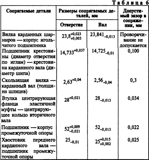
Check the condition of the centering sleeve of the flexible coupling. In case of significant wear or damage to the bushing, replace the flange assembly. Determine the condition of the center bearing by turning the inner race in both directions while pressing it against the outer race. In this case, the inner ring of the bearing should rotate smoothly, without jamming. Check bearing seals. If the bearing is worn or damaged, replace it with a new one. Check for damage or deformation of the intermediate support, if necessary, replace it with a new one. The main dimensions of the mating parts and the limits of permissible wear in operation are given in Table. 6.