




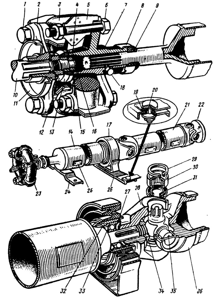
Fig. 126. Cardan transmission:
1 - bolt for fastening the elastic coupling to the flange of the secondary shaft of the gearbox; 2 - secondary shaft flange; 3 - rubber element of elastic coupling; 4 - flange centering sleeve; 5 - elastic coupling insert; 6 - bolt for fastening the elastic coupling to the flange of the front propeller shaft; 7 - front propeller shaft flange; 8 - oil seal cage; 9 - oil seal; 10 - secondary shaft of the gearbox; 11 - mud separator; 12 - secondary shaft flange fastening nut; 13 - centering ring seal; 14 - front propeller shaft; 15 - centering ring; 16, 27, 29 - retaining rings; 17 - intermediate support; 18 - cork; 19 - rubber bushing; 20 - spacer sleeve; 21 - rear propeller shaft; 22 - Cardan joint flange fork; 23 - elastic coupling; 24 - safety bracket; 25 - balancing plate; 26 - intermediate support crossbar; 28 - Front propeller shaft fork; 30 - needle bearing; 31 - oil seal; 32 - dust deflector; 33 - bearing; 34 - fork mounting nut; 35 - crosspiece; 36 - cardan joint fork.
The cardan shafts are made of thin-walled pipes, at the ends of which are welded: at the front cardan shaft splined ends, at the rear - cardan joint forks. On the splines of the front end of the front cardan shaft there is a flange 7, which through a rubber elastic coupling is connected to flange 2 of the secondary shaft 10 of the gearbox. The alignment of the connected shafts is ensured by a centering ring 15, pressed onto the end of the secondary shaft, and a centering sleeve 4, pressed into flange 7. Ring 15 is fixed on the shaft by a locking ring 16.
The splined connection is lubricated through an opening closed by plug 18. The lubricant is retained by rubber seal 9, which is placed in steel collar 8, and on the other side by seal 13, put on nut 12.
The rear splined end of shaft 14 rests on ball bearing 33 of the intermediate support. The fork 28 of the intermediate cardan joint is secured to the splines of the end with nut 34.
The intermediate support absorbs vibrations of the cardan transmission. It consists of a bracket secured to the crossbar with 26 bolts and nuts. The crossbar in turn is secured with nuts on bolts welded to the body. Steel spacer bushings 20 and rubber insulating bushings 19 are installed on the crossbar mounting bolts, pressed with washers. A rubber cushion is located in the bracket, which is vulcanized to the surface of the bracket and the bearing housing.
The original source is published on the website (vazbook.ru)
The bearing housing contains a radial ball bearing 33 with seals. The bearing is fixed in the housing with a retaining ring 27. Dust deflectors 32, installed on both sides of the bearing, protect the bearing from dirt. Litol-24 lubricant is added to the bearing during assembly and is not replenished during operation.
The elastic coupling absorbs noise and vibrations of the cardan transmission. It is made of six rubber elements 3, between which metal inserts 5 with holes for bolts 1 and 6 are placed. There are six projections on the inserts, three of which enter the grooves of the secondary shaft flange of the gearbox, and the rest - in the grooves of the elastic coupling flange. This ensures the centering of the elastic coupling on the flanges.
The cardan joint consists of two forks 28 and 36 fixed on the shafts and a crosspiece 35, which connects the forks together. The housings of the needle bearings 30 are put on the hollow pins of the crosspiece. The crosspiece bearing is sealed with an oil seal 31, located in a metal cage. The assembled needle bearings are fixed in the fork holes with retaining rings 29, which are divided into five sizes by thickness. Each size corresponds to a certain color: 1.62 - yellow; 1.59 - black; 1.56 - blue; 1.53 - dark brown; 1.50 — unpainted. By selecting a retaining ring of a certain thickness, the axial clearance of the crosspiece is provided at 0.01–0.04 mm.