
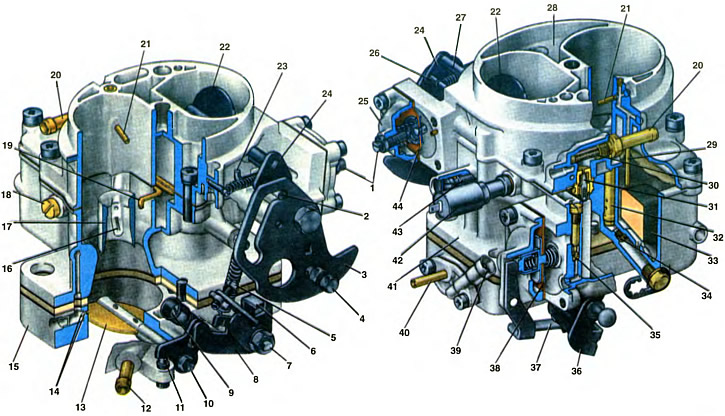
1. Trigger adjusting screw. 2. Lever pin 24, which fits into the groove of lever 3. 3. Choke control lever. 4. Screw for fastening the air damper drive rod. 5. Adjusting screw for slightly opening the throttle valve of the first chamber. 6. Throttle lever of the first chamber. 7. Throttle valve axis of the first chamber. 8. Throttle actuator lever of the second chamber. 9. Adjusting screw for the amount of idle mixture. 10. Throttle valve axis of the second chamber. 11. Throttle lever of the second chamber. 12. Pipe suction of crankcase gases into the throttle space of the carburetor. 13. Throttle valve of the second chamber. 14. Outlets of the transition system of the second chamber. 15. Throttle body. 16. Atomizer of the main dosing system of the second chamber. 17. Small diffuser. 18. Housing of the fuel jet of the transitional system of the second chamber. 19. Accelerator pump sprayer. 20. Fuel supply pipe to the carburetor. 21. Econostat atomizer. 22. Air damper. 23. The rod of the starting device. 24. Choke lever. 25. Starter cover. 26. Lever pin 24, acting from the rod 23 of the starting device. 27. Air damper axis. 28. Carburetor cover. 29. Tube with econostat fuel jet. 30. Fuel filter. 31. Needle valve. 32. Emulsion tube of the second chamber. 33. Float. 34. The main fuel jet of the second chamber. 35. Bypass jet of the accelerator pump. 36. Throttle actuator lever. 37. Accelerator pump drive lever. 38. Accelerator pump diaphragm. 39. Quality adjusting screw (composition) idle mixture. 40. Vacuum intake pipe of the vacuum ignition timing regulator. 41. Body of carburetors. 42. Electromagnetic shut-off valve. 43. Adjusting screw for additional air for factory adjustment of the idle system. 44. Diaphragm of the starting device.
On cars VAZ-1111 and VAZ-1113, a carburetor 1111-1107010 of an emulsion type is installed, two-chamber, with a falling flow, with sequential forced opening of the throttle valves. The throttle valves are opened from the carburetor control pedal in the car.
The carburetor has a balanced float chamber, a crankcase exhaust system into the throttle space of the second chamber, two main metering systems, a transition system and an idle system of the first chamber with an electromagnetic shut-off valve, a transition system of the second chamber, an econostat, a diaphragm accelerator pump, an inertial economizer, a diaphragm starting device.
The carburetor is mounted on the intake pipe with four studs and fastened with nuts.
The carburetor consists of three body parts: carburetor body 41, carburetor cover 28 and throttle body 15.
The carburetor cover 28 has inlets of the first and second mixing chambers, a well for passing air to the main air jets of the main metering systems, and float chamber balancing channels connecting the float chamber with the cavity behind the air filter element. An air damper 22 is installed in the neck of the first chamber. The lever 24 of the air damper has two pins, one of which has a spring that closes the air damper. The second pin 2 enters the groove of the lever 3 of the air damper control. The groove has a certain profile. Lever 3 is pivotally mounted on the carburetor cover and connected by a rod to the handle in the car.
Tubes with fuel jets of an econostat and an inertial economizer are installed on the carburetor cover. In the cover there are channels of an inertial economizer, an idling system, an econostat and channels of a starting device. It is attached to the cover 25 of the starter with an adjusting screw 1 and a diaphragm 44 of the starter assembly with the rod 23 of the device. A spring is installed under diaphragm 44.
A needle valve 31 for the fuel supply, a float 33, a fuel filter 30 and a branch pipe 20 for supplying fuel to the carburetor are installed in the carburetor cover. The float and needle valve ensure a constant fuel level in the float chamber. The level after pumping fuel into the chamber with the manual pumping lever and then removing the carburetor cover assembly with the float should be 22... 24 mm from the upper plane of the carburetor body. Adjustment of the fuel level is achieved by bending the tongue of the float lever.
A sealing gasket is installed between the cover and the carburetor body.
In the body 41 of the carburetor, large diffusers are cast in its two chambers and easily removable small diffusers 17 are installed, made integrally with the sprayers of the main dosing systems and the sprayer of the inertial economizer. Channels of the main dosing systems, idle system, transitional systems, inertial economizer, starting device and accelerator pump are made in the body.
In the carburetor body, sprayers 19 with an accelerator pump valve, main air jets with emulsion tubes 32, main fuel jets 34 are installed. an idle fuel jet with an electromagnetic shut-off valve 42, a housing 18 with a fuel jet of the transition system of the second chamber, air jets of the idle system and the transition system of the second chamber, the bypass jet 35 and the ball valve of the accelerator pump.
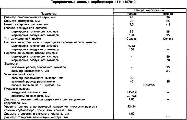
Fuel and air jets are marked (e.g. 95 or 170), which indicates the diameter of the orifice of the jet (0.95 mm or 1.75 mm). The marking is applied to the upper plane of the jet head or a cylindrical belt. The diameters of the jets are indicated in the carburetor calibration data table. In this case, it must be borne in mind that the factory is constantly improving the design of the carburetor and some data may change.
To the tide of the carburetor body, which forms the working cavity of the accelerator pump, its cover with the drive lever 37 and the diaphragm 38 of the accelerator pump are fastened with four screws. The accelerator pump is driven from a cam on axis 7 of the throttle valve of the first chamber. In the tide of the carburetor body, an adjusting screw 43 for additional air is supplied for the factory adjustment of the idle system.
The dampers of the first and second chambers are installed in the body 15 of the throttle valves. On the axis 7 of the throttle valve of the first chamber, a lever 6 is rigidly installed with a mustache included in the groove of the lever 8 of the throttle valve actuator of the second chamber. Lever 8 is freely mounted on axle 7 and is connected to a spring that closes damper 13. A throttle valve opening lever with adjusting screw 5 is rigidly mounted on axle 7. Throttle valve drive lever 36 with an accelerator pump cam is welded to the opposite end of axle 7. On the axis 10 of the throttle valve of the second chamber, the lever 11 is rigidly mounted with a slot for the pin of the lever 8.
When the lever 36 is turned, the throttle of the first chamber opens, after turning the damper by 2/3 of the full angle of rotation, the antennae of the lever 6, acting on the lever 8 with the pin. turns the lever 11 and opens the throttle valve 13 of the second chamber. Full opening of the throttle valves will occur simultaneously.
In the throttle body, the channels of the idle system and the transition system of the second chamber are made. In the tide of the body, an adjusting screw for the amount of the idle mixture is installed. In a separate housing mounted on the throttle body, an adjusting screw of 39 quality is supplied (composition) idling mixture and branch pipe 40 for vacuum intake of the vacuum ignition timing controller.
A branch pipe 12 for suction of crankcase gases into the throttle space of the carburetor is pressed into the throttle body. A calibrated hole with a diameter of 1.0 mm, which goes into the throttle space, does not have a noticeable effect on the lean mixture with closed throttle valves at idle.