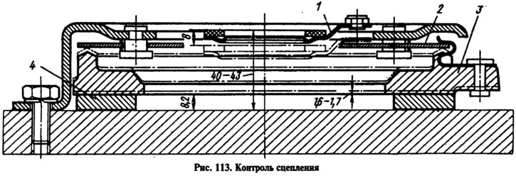
Fasten the clutch cover on the base, make 4 disengagement strokes, applying a load of no more than 140 kgf to the thrust flange 1 of the pressure spring 2. The disengagement stroke of 8 mm should correspond to the movement of the pressure disc 3 by 1.6-1.7 mm (smallest allowable 1.4 mm).
The distance from the base to the working surface of the friction lining of the thrust flange should be 40-43 mm. In the course of work, due to the wear of the friction surfaces of the clutch discs, this size increases. If it reaches 48 mm or the movement of the pressure plate is less than 1.4 mm, replace the clutch cover assembly with the pressure plate, pressure spring and thrust flange.
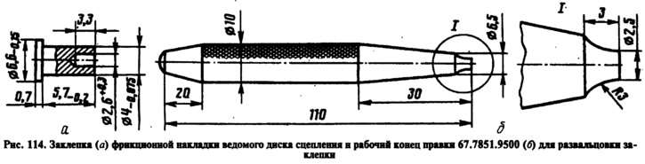
Replace the friction linings of the driven disk if cracks appear, if the distance between the rivet and the working surface decreases to 0.2 mm, if there are scoring on one side. At the same time, drill old rivets with a drill or knock out with a punch. New rivets (pic. 114, a) flared with mandrel 67.7851.9500 (pic. 114b).
The runout of the working surface of the friction linings of the driven disk should not exceed 0.5 mm. If it is greater, then the disk is straightened by bending the part where the beating is detected, or replaced with a new one.
If cracks appear on the driven disk or damper springs or the splines in the hub are worn, replace the driven disk assembly.
The cylinder mirror and the outer surface of the pistons of the main and working cylinders must not be damaged or corroded; Small burrs or pitting found should be repaired with a fine sanding stone. Check the condition of the master cylinder piston return spring and replace it if it is cracked. Replace O-rings regardless of their condition. Check protective caps; if they are damaged, replace with new ones. Deformation of pushers is not allowed.
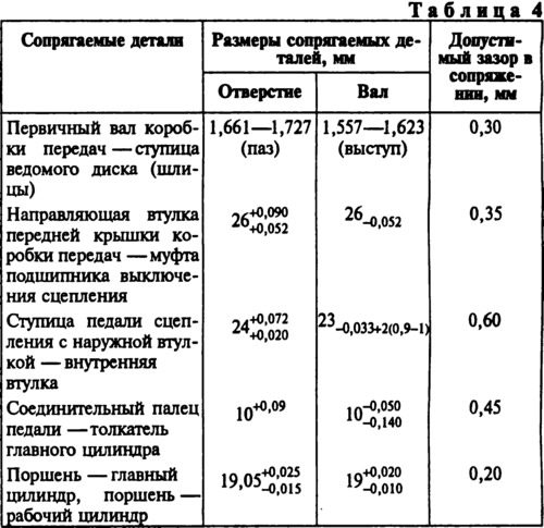
The dimensions of the main mating parts of the clutch and the limits of permissible wear are given in Table. 4.