
The car is equipped with a dry, single-plate clutch, permanently closed type, with a central pressure spring and a torsional vibration damper (damper) on the slave drive.
The clutch is located on the flywheel 7 (pic. 56) and is covered by an aluminum crankcase, which is attached to the engine block. From the side of the engine to the end surface of the clutch housing, the upper and lower covers lean, on the reverse side - the gearbox housing. A scale 9 with divisions is welded on the inside of the top cover, and a mark is made on the flywheel. According to mime set and check the moment of ignition. For this purpose, there is an inspection hatch in the upper part of the clutch housing. In addition to it, at the top of the crankcase 1 there is a hole for a plastic sleeve 14 of the clutch release fork. The lower end of the fork rests on a metal sleeve 2 pressed into the clutch housing boss hole.
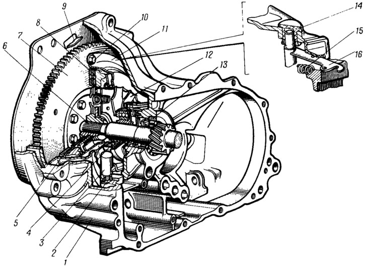
Pic. 56. Clutch assembly:
1 - clutch housing; 2 - support sleeve of the clutch release fork; 3 - clutch release fork; 4 - clutch release bearing; 5 - driven disk; 6 - the input shaft of the gearbox; 7 - flywheel; 8 - pressure plate; 9 scale for checking the ignition timing; 10 - a bolt of fastening of coupling to a flywheel; 11 - clutch cover; 12 - clutch pressure spring; 13 - bearing of the input shaft of the gearbox; 14 - clutch release fork bushing; 15 - withdrawal spring of the clutch fork lever; 16 - clutch release fork lever.
The leading part of the clutch is a non-separable assembly, consisting of a casing 11, a pressure plate 8, a pressure spring 12 and a number of other parts. This assembly is attached to the flywheel with six bolts 10. The accuracy of the installation of the assembly on the flywheel is ensured by three pins.
Pressure plate 11 (pic. 57) is connected by three pairs of elastic plates 12 with the casing 13 of the clutch. Such an elastic connection ensures the transmission of torque from the clutch housing to the pressure plate, as well as axial movement of the pressure plate in the casing when the clutch is released. In addition, the connecting plates, due to their elasticity, divert the pressure plate from the driven disc when the clutch is released.
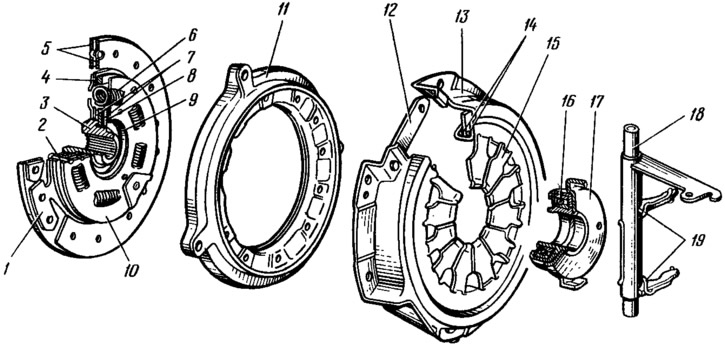
Pic. 57. Clutch (detailing):
1 - driven disk; 2 thrust pin; 3 - hub of the driven disk; 4 - front plate of the damper of torsional vibrations (damper); 5 - friction linings; 6 - damper spring; 7 - friction ring; 8 - support ring; 9 - spring washer; 10 - rear damper plate; 11 - pressure plate; 12 plate connecting the clutch cover and pressure plate; 13 - clutch cover; 14 - support rings of the pressure spring; 15 - pressure spring; 16 - clutch release bearing; 17 - clutch release bearing; 18 - clutch release fork; 19 - connecting spring of the fork and clutch of the clutch release bearing.
Due to the rigid connection of the leading part of the clutch with the flywheel, the torque from it is transmitted directly to the parts of the leading part of the clutch, both in the on and off position.
Clutch cover 13 - steel, stamped. On the outer flange of the casing there are holes for bolts and pins that fasten it to the flywheel, and on the inner flange there are twelve protrusions, the ends of which are bent inside the casing by 100...110°. Due to this, sockets are formed for support rings 14, which are welded to the clutch housing. These rings are supports for the pressure spring 15, relative to which it deflects when the clutch is released.
The pressure spring is stamped from sheet spring steel in the form of a truncated cone. The inside of the pressure spring has radial slots that end in square holes. The protrusions of the clutch cover enter these holes, which are then bent. The slots form petals on the surface of the spring, which act as clutch release levers. The ends of the petals at the point of contact with the clutch release bearing are bent to a rounding.
The pressure plate 11 is cast iron. It has three lugs with holes for rivets, which are used to fasten the elastic plates 12. There are twelve ventilation slots on the annular protrusion of the disk.
The driven part of the clutch consists of a driven disk 1 assembled with friction linings 5 and a torsional vibration damper (damper). The driven disk is steel, with curly slots dividing it into eight petals. Each petal has a flat area and two bends (bulges), due to which the surface of the steel disk has a wavy shape. To maintain this shape, friction linings 5 are riveted to each petal independently of each other, one to the convex part of the petal, the other (opposite) - to a flat area. The heads of the rivets are buried in the holes of the linings, and their rods are riveted from the side of the disk. Holes are made in the opposite lining to access the rivets.
The convex part of the petals creates an uneven specific pressure on the surface of the linings and the surfaces of the flywheel and pressure plate in contact with them: it is greater under the convex part of the petal, and less in the spaces between them. Only after the driven disk is fully compressed, the specific pressure on these surfaces is equalized, which ensures smooth engagement of the clutch. In this case, the initially driven disk slips relative to the surfaces of the flywheel and pressure plate, and the transmitted torque increases gradually. This protects the transmission parts from overloads and contributes to smooth starting of the car.
The driven disk is connected to the hub 3 through the parts of the torsional vibration damper, which creates an elastic connection between them. The need for a vibration damper is caused by the following. With a sharp change in the speed of the car, hitting bumps in the road, abrupt engagement of the clutch, and also due to uneven torque during the four-stroke cycle of the engine, dynamic loads occur in the car transmission, causing twisting (unwinding) transmission shafts. The uneven torque of the engine can cause significant overloads in the transmission due to the occurrence of torsional vibrations and resonance when the frequencies of the transmitted loads coincide with the natural frequencies of the transmission. Elastic oscillations of the transmission lead not only to the appearance of noise in mechanisms and assemblies, but also to dangerous vibrations, sometimes to breakage of parts, when the oscillation amplitudes reach a large value. The energy of torsional vibrations is absorbed by the absorber (damper).
It includes: front 4 and rear 10 plates, springs 6, thrust pins 2, friction rings 7, support ring 8 and spring washer 9. The listed parts connect hub 3 with driven disk 1. Flange 3 is clamped between friction rings 7 by plates 4 and 10, which are connected to each other and to the driven disk with thrust fingers 2 (rivets). These fingers pass freely through the three horseshoe cutouts of the hub flange and limit the angle of rotation of the driven disk (together with damper plates) regarding the hub. Friction rings 7 (one steel, the other friction material) are pressed against the hub flange with a conical spring washer 9 through the support ring 8 with a force that ensures the movement of the driven disk relative to the hub (to the fingertips) at a torque of 12 kgf-m. Additional resistance to the rotation of the disk 1 relative to the hub is created by three pairs of springs 6 of different elasticity and coloring (coatings), laid in rectangular windows of the hub, disk and plates 4 and 10. Springs of the same color are located opposite each other. From falling out of the windows of the hub and the disk, the springs are fixed by windows in plates 4 and 10, the size of which is smaller than the diameter of the springs.
The damping of torsional vibrations occurs due to the friction forces that arise when the disk 1 and plates move relative to the hub 3 and due to the elasticity of the springs. The amplitude of action of the elastic element of the damper of torsional vibrations is limited by three fingers 2, which abut against the horseshoe cutouts of the hub.
The clutch is disengaged by means of a cable drive, the force from which through the lever 16 (see fig. 56) is transmitted to the clutch release bearing 4.
The clutch assembly with the clutch release bearing is located on the guide sleeve, which tilts towards the clutch housing with its flange. To the protrusions of the clutch with a spring 19 (see fig. 57) the fork 18 of the clutch is pressed. She turns on 2 bushings (see fig. 56) and 14. The exit point of the lever from the crankcase is sealed with a protective cover.