
Checking the left lower arm
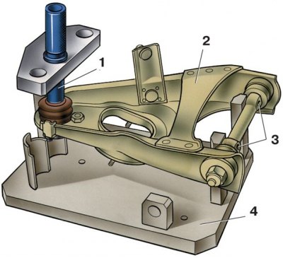
1 - mandrel for centering the ball joint; 2 - lower lever; 3 - hole for the mounting fingers of the device A.95716; 4 - fixture A.95716 for checking the levers
Checking the left upper arm
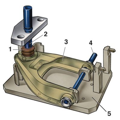
1 - ball joint; 2 - mandrel for centering the ball joint; 3 – the top lever; 4 - pin for centering hinges; 5 - fixture A.95716
The deformation of the upper and lower arms is determined on fixture A.95716.
Install the lower arm so that the mandrel 1 (see pic. Checking the left lower arm) for centering, it was articulated with the cone of the pin of the ball joint of the lever, and the locating fingers of the device entered the holes of the 3rd axis of the lever.
The centering mandrel must fit into the right or center hole of the device, respectively, depending on which lever is being checked, right or left.
A sign of the deformation of the lever is the impossibility of inserting the fixture into the holes 3 of the lever axis without the effort of the fingers, as well as poor articulation of the mandrel 1 with the cone of the ball joint pin.
The upper arm is mounted on the fixture (see pic. Checking the left upper arm) in an inverted position so that the mandrel 2 for centering exactly coincides with the shank of the pin of the ball joint 1, and the pin 4 passes into the holes of the rubber-metal hinges of the lever.
The magnitude of the deformation of the lever is determined by the difficulty of inserting the pin 4 into the holes of the hinges of the levers and by the poor articulation of the conical socket of the mandrel 2 with the conical surface of the pin of the ball joint 1. The pin 4 should enter the holes of the hinges without much effort. With a small deformation, the levers are corrected, and with a large one, they are replaced.