




Marks on the main bearing caps and the cylinder block reference number
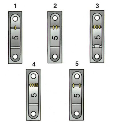
The number of supports is calculated from the front of the engine.
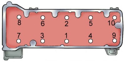
Cylinder Head Bolt Tightening Sequence
Installing the oil pump drive gear and ignition distributor
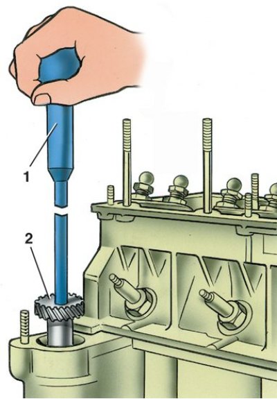
1 – mandrel 41.7820.4006; 2 – gear
1. Place the washed and cleaned cylinder block on the stand and tighten the missing studs.
2. Place a bearing shell without a groove on the inner surface in the middle bearing seat, and bearing shells with a groove in the other seats.
3. The bearing caps are fitted with liners without grooves.
Attention! Lubricate the engine cylinders, as well as the pistons and seals, bearing shells and crankshaft thrust half rings with engine oil before installation.
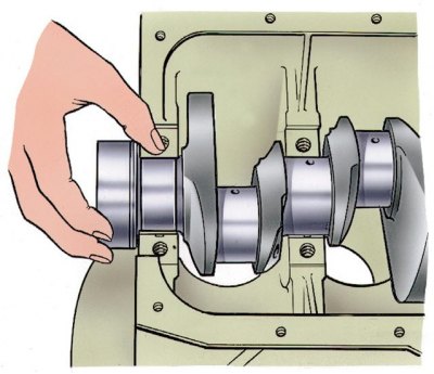
4. Place the crankshaft in the main bearings and insert two thrust half rings of the correct thickness into the rear support sockets.
5. Install the main bearing caps according to the marks (see fig. Marks on the main bearing caps and the conventional number of the cylinder block).
Attention! Install the main bearing caps into the previous block. For this purpose, the cylinder block and the caps belonging to it are marked with the same reference number (see Fig. Marks on the main bearing caps and the reference number of the cylinder block and Fig. Marking of the cylinder size group on the block and the conventional number of the cylinder block). Install the thrust half rings with the recesses towards the thrust surfaces of the crankshaft, and install a steel-aluminum half ring on the front side of the rear support, and a metal-ceramic half ring on the rear side (yellow color).
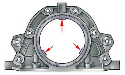
6. Place the oil seal holder gasket on the crankshaft flange and insert the front clutch housing cover mounting bolts into the holder sockets (the arrows indicate the protrusions for centering the holder relative to the crankshaft flange). Place the holder with the oil seal on the mandrel 41.7853.4011 and, moving it from the mandrel to the crankshaft flange, attach it to the cylinder block.
7. Install the front cover 6 using two centering bushings (see Fig. Removal the flywheel) clutch housing.
8. Install the flywheel on the crankshaft so that the mark (cone-shaped hole) near the rim was opposite the axis of the connecting rod journal of the fourth cylinder, lock the flywheel with the A.60330/R lock and attach it with bolts to the crankshaft flange.
9. Match the pistons to the cylinders (see subsection 4.8.3) and assemble the pistons with the connecting rods (see subsection 4.8.8).
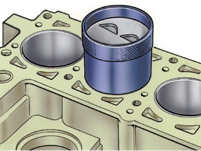
10. Using the bushing from the 02.7854.9500 set, insert the pistons with connecting rods into the cylinders. The set consists of three bushings: one for normal-size pistons and two for oversize pistons (increased by 0.4 and 0.8 mm). Therefore, it is necessary to select a bushing suitable for the given size of the piston being installed.
Attention! The pin hole on the piston is offset by 2 mm, so when installing the pistons into the cylinders, the "P" mark on the pistons must face the front of the engine.
11. Install the connecting rod liners and connecting rod caps. Connect the connecting rods to the crankshaft journals, install the caps and tighten the connecting rod bolts.
12. Install the oil pump drive shaft and secure with the thrust flange.
13. Install the cylinder head with gasket, exhaust manifold and intake manifold on the block using two centering bushings. Tighten in a specific sequence (see Fig. Cylinder Head Bolt Tightening Sequence) in two steps fastening bolts:
- pre-torque 33.3–41.16 N·m (3.4–4.2 kgf·m);
- finally with a torque of 95.94–118.38 N·m (9.79–12.08 kgf·m).
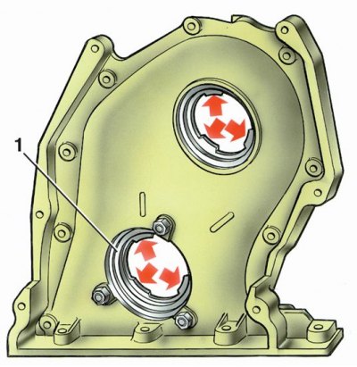
14. Attach the holder 1 of the oil seal with the gasket to the camshaft drive cover (the arrows indicate the protrusions for centering the holder and cover relative to the crankshaft and the oil pump drive shaft), without completely tightening the fastening nuts.
15. Attach the camshaft drive cover with the gasket to the cylinder block without fully tightening the mounting nuts and bolts.
16. Center the position of the cover relative to the shaft 6 using mandrel 67.7853.9548 (see Fig. Disassembling the front part of the engine) oil pump drive and tighten the bolts and nuts securing the camshaft drive cover.
17. Using drift 67.7853.9549, center the position of the holder 1 of the front crankshaft oil seal and tighten the holder mounting nuts.
18. Install pulley 8 (see Fig. Disassembling the front part of the engine) onto shaft 6 of the oil pump drive, without tightening the pulley mounting bolt. Install toothed pulley 9 on the crankshaft.
Attention! The bolt for fastening the pulley of the oil pump drive shaft must be installed using sealant according to TU 6-10-1048-73 or sealant TV-1215 from "Three Bond".
19. Assemble the camshaft bearing housing (see subsection 4.11.8).
20. Clean the mating surfaces of the cylinder head and holder 6 (see Fig. Removal the cylinder head) camshaft oil seal from the remains of the old gasket, dirt and oil.
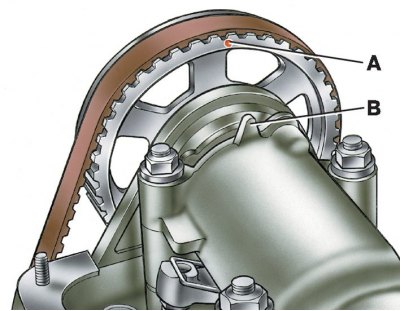
21. Apply KLT-75TM sealant or a similar TV-1215 sealant to the surface of the cylinder head mating with the oil seal holder "Three Bond". Turn the camshaft so that the marks on the pulley and bearing housing are aligned (A – mark on the pulley, B – mark on the bearing housing).
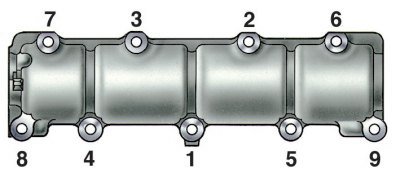
22. Without disturbing the position of the shaft, secure the assembled bearing housing to the cylinder head, tightening the nuts in a specific sequence.
Attention! The engine may be started 1 hour after applying the liquid gasket.
23. Attach the bracket with the tension roller to the cylinder block without fully tightening the mounting bolts. Turn the bracket to the extreme left position.
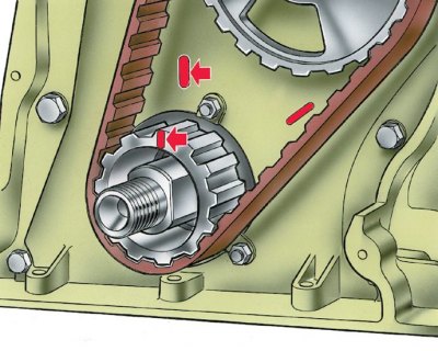
24. Turn the crankshaft so that the mark on the toothed pulley coincides with the mark on the camshaft drive cover.
25. Place the belt on the pulleys and on the tension roller, press the tension roller bracket to the right and install the tension spring.
26. Smoothly rotate the crankshaft two revolutions, keeping the belt under constant tension, and when the shaft stops, hold it, preventing the belt from loosening. In this way, the spring will set the required belt tension. Tighten the tension roller bracket mounting bolts.
27. Check that the marks match. If the marks do not match, reinstall the belt.
28. Adjust the clearance between the camshaft lobes and the valve drive levers.
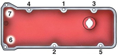
29. Install the cylinder head cover with the gasket and tighten the mounting nuts in the sequence shown in the figure. Install the camshaft belt drive protective covers.
30. Install the generator drive pulley and secure it with a ratchet.
31. Lubricate the oil filter O-ring with oil and install it by hand-tightening it to the fitting on the adapter. Install the crankcase ventilation oil separator, breather cap and secure the oil separator drain tube retainer.
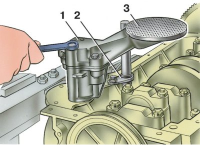
32. Install the oil pump (1 – oil pump, 2 – drain pipe retainer, 3 – oil separator drain pipe) and oil pan with gasket.
33. Install the coolant pump, alternator bracket and alternator. Place the belt on the pulleys and adjust its tension.
34. Install the heater radiator inlet pipe and outlet pipe on the cylinder head. Attach the heater radiator outlet pipe to the coolant pump and outlet manifold.
35. Install control instrument sensors.
36. Install the oil pump and distributor drive gear (see Fig. Installing the oil pump drive gear and ignition distributor). Install the ignition distributor. Screw in the spark plugs, install the 67.7812.9515 key on them and tighten with a torque wrench.
37. Install the fuel pump according to the instructions (see subsection 4.14.2).
38. Install the carburetor, connect the hoses to it and close it with a technological plug.
39. Pour oil into the filler neck on the cylinder head cover.