

Three unified engines with a working volume of 1100, 1300 and 1500 cm33 are formed by a combination of three blocks differing in height and diameter of cylinders, two cylinder heads with inlet channels of different diameters, as well as two pistons differing in diameter (76 and 82), and two crankshafts with crank radii corresponding to piston strokes of 60.6 and 71 mm.
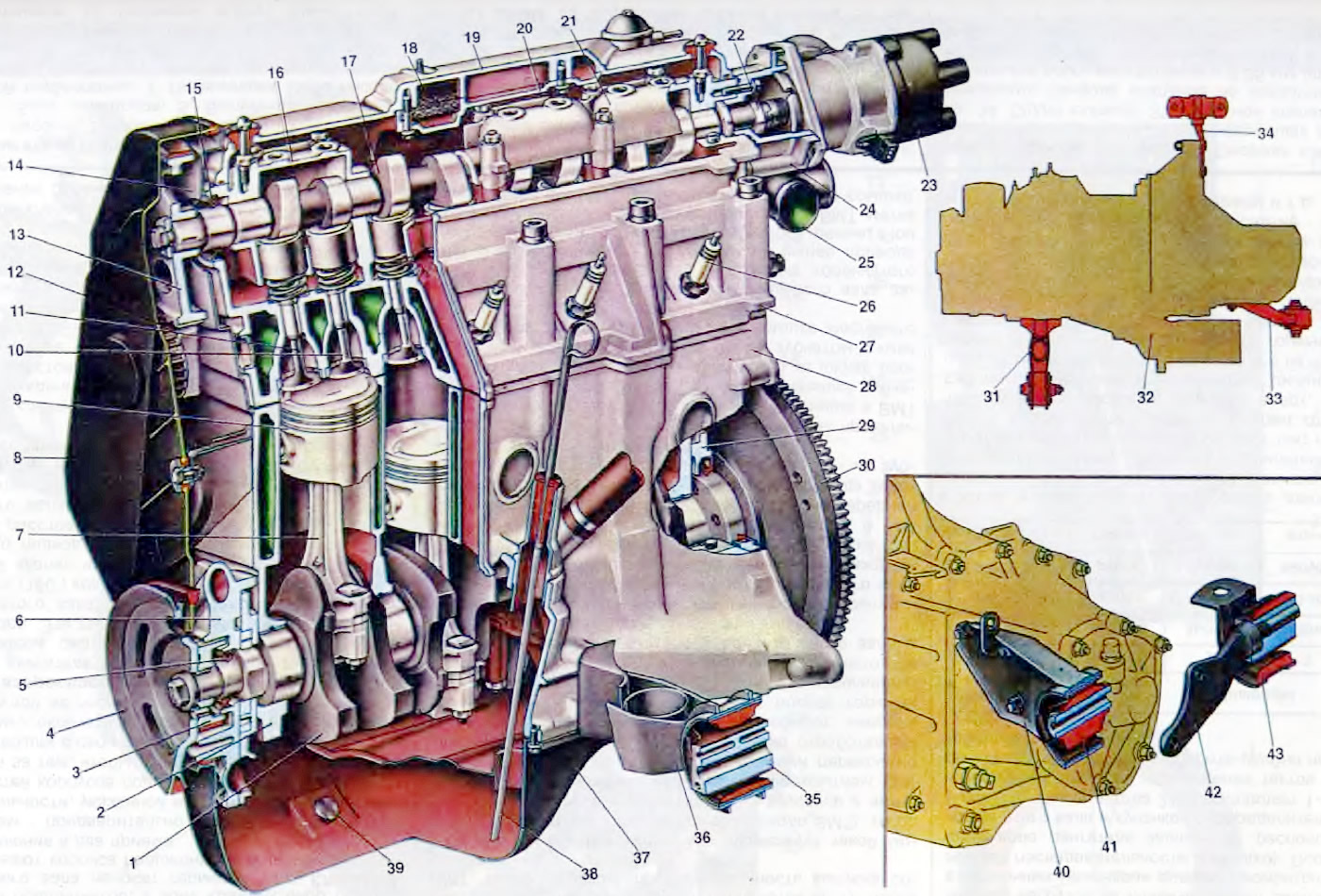
Together with the gearbox and clutch, the engine forms a single rigid unit - the power unit. It is installed on the car on three elastic supports. They perceive both the mass of the power unit and the loads that occur when the car starts off, accelerates and brakes. Elastic mounts absorb vibrations of a running engine and do not transmit them to the body, thereby reducing noise in the car. On the other hand, elastic mounts protect the power unit from sharp shocks when the car moves over uneven roads.
The car adopted a three-point mounting scheme for the power unit, consisting of front, rear and left supports. The front and left bearings have the same device and consist of an outer steel cage and an inner aluminum bushing, between which there is rubber vulcanized to them.
The rear support is bolted from below to the bottom of the body. It consists of an outer steel reinforcement and an inner aluminum sleeve, also separated by rubber. Rear suspension bracket - steel, forged, mounted on the gearbox with bolts connecting the clutch housing to the gearbox housing.
Cylinder block
All engine cylinders are combined together with the upper part of the crankcase into one common unit - a cylinder block cast from special high-strength cast iron. With this arrangement, structural strength, rigidity, compactness are ensured and the mass of the engine is reduced. The coolant channels are made along the entire height of the cylinder block, which improves the cooling of the pistons and piston rings and reduces the deformation of the cylinder block from uneven heating.
The cylinders of the block are subdivided into five classes according to their diameter, every 0.01 mm. denoted by the letters A, B, C, D, E:
| Class | Engine cylinder diameter 21081, 2108, mm | Engine cylinder diameter 21083, mm |
| A | 76,000-76,010 | 82,000-82,010 |
| IN | 76,010-76,020 | 82,010-82,020 |
| WITH | 76,020-76.030 | 82,020-82,030 |
| D | 76,030-76,040 | 82,030-82,040 |
| E | 76,040-76,050 | 82,040-82,050 |
The cylinder class is indicated on the bottom plane of the block against each cylinder. The cylinder and the piston mating with it must be of the same class. During repair, cylinders can be bored and honed to fit an increased piston diameter of 0.4 and 0.8 mm.
In the lower part of the cylinder block, there are five crankshaft main bearing supports with thin-walled steel-aluminum liners Upper and lower liners of the middle (3rd) main bearing without a groove on the inner surface. The remaining supports have upper liners with a groove on the inner surface, and lower ones without a groove. Until 1988, the lower shells of these bearings were also grooved.
The bearings have removable covers 2, which are attached to the cylinder block with self-locking bolts. The holes for the crankshaft bearings in the cylinder block are machined complete with covers, which ensures high accuracy, the correct geometric shape of the holes and their alignment. Therefore, bearing caps are not interchangeable and have risks on the outer surface to distinguish (see fig. 6).
Open large image in new tab »
Pic. 6. Engine (lengthwise cut): 1. Crankshaft; 2. Cover of the first main bearing; 3. Camshaft drive pulley; 4. Generator drive pulley; 5. Front crankshaft oil seal; 6. Oil pump; 7. Connecting rod; 8. Front protective cover of the toothed belt; 9. Piston; 10. Inlet valve; 11. Exhaust valve; 12. Camshaft drive belt; 13 Camshaft pulley; 14. Back protective cover of a gear belt; 15. Camshaft oil seal; 16. Front camshaft bearing housing; 17. Camshaft; 18. Mesh oil separator of the crankcase ventilation system; 19. Cylinder head cover; 20. Oil separator cover; 21. Rear camshaft bearing housing; 22. Fuel pump drive eccentric; 23. Sensor-distributor ignition; 24. Housing of auxiliary units; 25. Outlet pipe of the cooling jacket; 26. Spark plug; 27. Cylinder head; 28. Block of cylinders; 29. Holder with rear crankshaft oil seal; 30. Flywheel; 31. Bracket with support for the front engine mount; 32. Power unit (engine with gearbox and clutch); 33. Bracket with support for the left engine mount; 34. Bracket with support for the rear engine mount; 35. Front engine mount support; 36. Bracket front engine mount; 37. Oil sump; 38. Oil level indicator; 39. Plug hole for draining oil from the crankcase; 40. Bracket left engine mount; 41. Support left engine mount; 42. Bracket rear engine mount; 43. Support rear engine mount.
In the middle support there are sockets for the installation of thrust half rings 12 (see fig. 6). holding the crankshaft from axial movement. A ceramic-metal half ring is placed on the back side of the middle support (yellow color), and from the front side - steel-aluminum.
The value of the axial clearance of the crankshaft should be 0.06-0.026 mm. If the clearance exceeds the maximum allowable (0.35 mm), it is necessary to replace the half rings with repair ones, increased by 0.127 mm. It should be borne in mind that the grooves located on one side of the half rings must face the thrust surfaces of the crankshaft.
From below, the cylinder block is closed with a stamped steel crankcase 37. The crankcase has a baffle to calm the oil. Between the oil crankcase and the cylinder block, a cork-rubber mixture gasket is installed.
The clutch housing is attached to the rear end of the cylinder block. The exact location of the crankcase relative to the cylinder block and the alignment of the crankshaft and the input shaft of the gearbox is ensured by two centering bushings pressed into the cylinder block.
Cylinder head
Cylinder head 27 is common to four cylinders. cast from aluminum alloy, has a wedge-shaped combustion chamber. Valve guides and saddles made of cast iron are pressed into the head. The seats, pre-cooled in liquid nitrogen, are inserted into the seats of the heated cylinder head. This ensures a secure and firm fit of the seats in the head.
A special non-shrink gasket on a metal frame is installed between the head and the cylinder block. The head is centered on the cylinder block with two bushings and is attached to it with ten bolts.
Open large image in new tab »
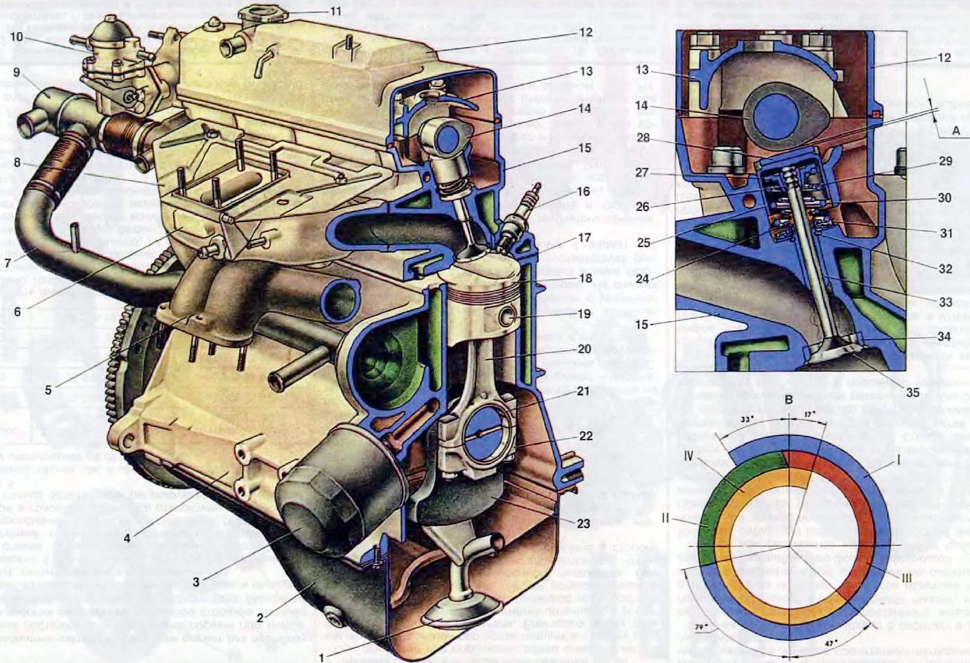
Pic. 7. Engine (cross section): 1. Oil pump receiver; 2. Oil sump; 3. Oil filter; 4 cylinder block; 5. Exhaust manifold; 6. Inlet pipeline; 7. Supply pipe of the coolant pump; 8. Carburetor heat shield; 9 Thermostat; 10. Fuel pump; 11. Oil filler cap; 12. Cylinder head cover; 13. Front camshaft bearing housing; 14 Camshaft; 15. Cylinder head; 16. Spark plug; 17. Cylinder head gasket; 18. Piston; 19. Piston pin; 20. Connecting rod; 21. Insert connecting rod bearing of the crankshaft; 22. Connecting rod cap; 23. Crankshaft; 24. Oil cap; 25. Pusher; 26 Valve cotter; 27. Spring plate; 28. Adjusting washer; 29. Internal valve spring; 30. Outer valve spring, 31. Spring support washer; 32. Retaining ring; 33. Valve guide; 34. Valve seat; 35. Inlet valve; A. Clearance in the valve drive mechanism on a cold engine: 0.2 mm for intake valves and 0.35 mm for exhaust; B. Valve timing diagram; I. Combustible mixture inlet; II. Compression; III. working stroke; IV. Release.
For uniform compression of the entire surface of the block head gasket, to ensure reliable sealing and to prevent subsequent tightening of the bolts during vehicle maintenance, the cylinder head bolts are tightened evenly without jerks in four steps and in a strictly defined sequence (see fig. 7):
- 1 reception - tighten the bolts with a torque of 2 kg cm;
- 2 reception - tighten the bolts with a torque of 7.08-8.74 kg cm,
- 3 reception - turn the bolts 90°;
- 4 reception - again tighten the bolts by 90°.
In the upper part of the cylinder head there are five bearings for the camshaft journals 17. The bearings are split. The upper half is in bearing housings 16 and 21 (front and rear), and the lower one is in the cylinder head. The locating bushings of the camshaft bearing housings are located at the housing mounting studs. The bearing bores are machined complete with the bearing housings, so they are not interchangeable and the cylinder head can only be replaced complete with the bearing housings.
Sealant of the KLT-75TM type is applied on the surfaces of the cylinder head mating with the bearing housings in the area of the extreme camshaft bearings. Install the bearing housings and tighten the nuts of their fastening in two stages.
- 1st method - pre-tighten the nuts in the sequence indicated on sheet 7 until the surfaces of the bearing housings touch the cylinder head, making sure that the mounting sleeves of the housings freely enter their sockets;
- 2nd reception - finally tighten the nuts with a torque of 2.2 kg / cm in the same sequence.
Gas distribution phases. In one working cycle, four cycles occur in the engine cylinder - the intake of a combustible mixture, compression, power stroke and exhaust gases. These cycles are carried out in two revolutions of the crankshaft, i.e. each beat takes half a turn (180°) crankshaft.
The inlet valve starts to open ahead of time, i.e. until the piston reaches top dead center (TDC) at a distance corresponding to 33 * crankshaft rotation to TDC. This is necessary so that the valve is fully open when the piston goes down, and as much fresh combustible mixture as possible enters through the fully open inlet.
The inlet valve closes with a delay, i.e. after the pistons have passed bottom dead center (NMT) at a distance corresponding to 79 ' of rotation of the crankshaft after BDC Due to the inertial pressure of the jet of the intake combustible mixture, it continues to flow into the cylinder when the piston has already begun to move upward, and thus better filling of the cylinder is ensured. Thus, the intake practically occurs during the rotation of the crankshaft by 292°.
The exhaust valve begins to open even before the end of the working stroke, before the piston approaches BDC by a distance corresponding to 47°of crankshaft rotation to BDC. At this moment, the pressure in the cylinder is still quite high, and the gases begin to rapidly flow out of the cylinder, as a result of which their pressure and temperature drop rapidly. This significantly reduces engine work during exhaust and prevents the engine from overheating.
The release continues even after the piston has passed TDC. those. when the crankshaft rotates 17°after TDC. Thus, the duration of release is 244°.
It can be seen from the phase diagram that there is such a moment (50°of rotation of the crankshaft near TDC), when both valves, intake and exhaust, are open at the same time. This position is called valve overlap. Due to the short time interval, the overlapping of the valves does not lead to the penetration of exhaust gases into the intake manifold, but, on the contrary, the inertia of the exhaust gas flow causes the combustible mixture to be sucked into the cylinder and thereby improves its filling.
The described valve timing takes place with a gap A between the camshaft cam and the valve tappet on a cold engine.
To ensure the timing of the opening and closing of the valves with the angles of rotation of the crankshaft (i.e. to ensure the correct installation of the valve timing), there are marks on engine parts (see fig. 7) 7 - on the back cover of the toothed belt; 8 - on the camshaft pulley; 10 and 11 - on the front cover of the toothed belt; 12 - on the generator drive pulley; 13 - on the cover of the oil pump; 14 - on the toothed pulley of the crankshaft.
If the valve timing is set correctly, then with the position of the piston of the first cylinder at TDC at the end of the compression stroke, mark 7 on the rear cover of the toothed belt must match mark 8 on the camshaft pulley, and mark 14 on the crankshaft toothed pulley should match mark 13 on the oil cover pump.
When the camshaft drive cavity is closed by the front cover, the position of the crankshaft can be determined by the marks on the alternator drive pulley and the front toothed belt cover. When the piston of the fourth cylinder is at TDC, mark 12 on the pulley must match mark 11 on the camshaft drive cover. In addition, you can use the label 20 (see fig. 6) on the flywheel and scale 19 in the hatch of the clutch housing. One division of the scale corresponds to a rotation of the crankshaft by 1°. If the marks match, the belt tension and clearances A in the valve mechanism are adjusted.
Order of engine operation For smooth operation of a multi-cylinder engine and to reduce uneven loads on the crankshaft, the work processes in different cylinders must occur in a certain sequence (okay). The order of operation of the engine cylinders depends on the location of the crankshaft journals and camshaft cams, and for engines of the 2108 family it is 1-3-4-2.
The sequence of alternation of cycles in the engine cylinders for two full revolutions can be conveniently traced from the table:
| Half turns of the crankshaft (deg.) | cylinders | |||
| 1 | 2 | 3 | 4 | |
| 1st (180°) | working stroke | release | compression | inlet |
| 2nd (360°) | release | inlet | working stroke | compression |
| 3rd (540°) | inlet | compression | release | working stroke |
| 4th (720°) | compression | working stroke | inlet | release |
When in the first cylinder the piston moves down in the range from 0°to 180°of rotation, combustion and expansion of gases occurs. During expansion, gases do useful work, so this cycle is called a working stroke. The third cylinder lags behind the first by 180°. and in it the piston moves upward, compressing the working mixture. In the fourth cylinder, lagging behind the first by 360°, and from the third by 180°, the piston moves down, and the combustible mixture is admitted. And, finally, in the second cylinder, lagging behind the cycle of the working process by 540°from the first cylinder, at this time the piston moves up, and the exhaust gases are released. Similarly, in the range from 180°to 360°of rotation of the first crankpin, the power stroke occurs in the third cylinder, compression in the fourth, intake in the second and exhaust in the first, etc.