
Clutch assembly
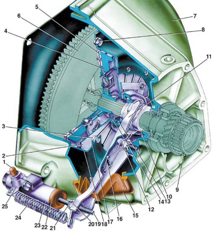
1 - fitting for pumping; 2 - clutch pressure spring; 3 - stepped rivet pressure spring; 4 - pressure plate; 5 - driven disk; 6 - flywheel; 7 - clutch housing; 8 – a bolt of fastening of a casing of coupling to a flywheel; 9 – a primary shaft of a transmission; 10 - clutch release bearing; 11 - clutch release fork; 12 - ball joint of the clutch release fork; 13 - clutch release bearing; 14 - thrust flange of the pressure spring; 15 – a cover of a plug of deenergizing of coupling; 16 - fork spring; 17 – a basic ring of a pressure spring; 18 - clutch cover; 19 – a pusher of a plug of deenergizing of coupling; 20 - adjusting nut; 21 - locknut; 22 - protective cap; 23 - clutch release cylinder (working cylinder); 24 - retraction spring of the fork; 25 - bracket of the withdrawal spring
Slave cylinder and clutch release fork
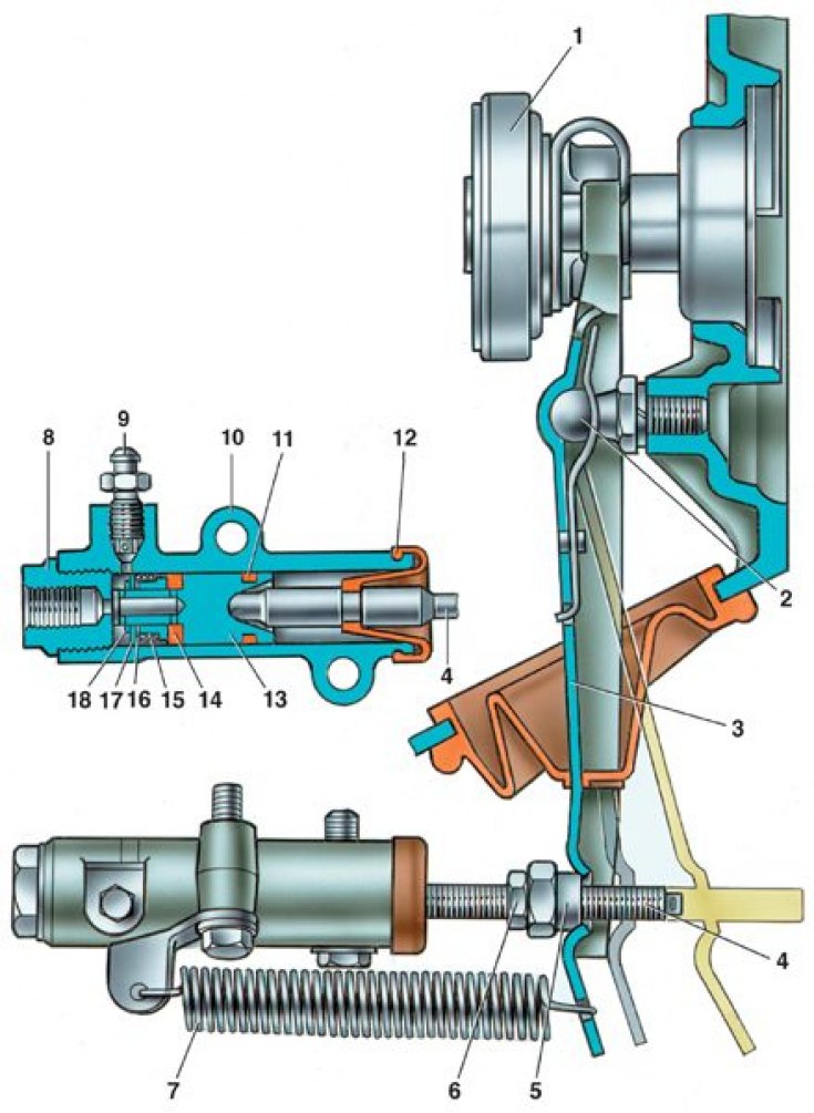
1 - clutch release bearing; 2 - ball bearing; 3 - clutch release fork; 4 - pusher; 5 - adjusting nut; 6 - locknut; 7 - withdrawal spring; 8 – body plug; 9 - fitting for pumping; 10 - cylinder body; 11 - sealing ring; 12 - protective cap; 13 - piston; 14 - sealant; 15 - plate; 16 - spring; 17 - support washer; 18 - retaining ring
The car is equipped with a single-disk, dry, permanently closed clutch with a central pressure spring and a torsional vibration damper on the driven disk.
The leading part of the clutch is a non-separable unit, includes a casing 18 (see fig. Clutch assembly) clutch, pressure plate 4 and diaphragm pressure spring 2. The clutch cover is attached to the flywheel 6 with dowel pins and bolts 8. The pressure plate 4 is connected to the casing 18 by three pairs of steel plates, each of which is riveted to the casing at one end and to the pressure plate at the other. Through the clamps, the pressure plate is connected to the outer edge of the diaphragm spring 2, which rests on two rings 17 of circular cross section, fixed on the casing with stepped rivets 3.
Driven disk 5 is made of steel, has slots that divide it into twelve sectors, bent in different directions. Friction linings are riveted to the sectors of the disk, independently of each other. To dampen torsional vibrations, the driven disk is connected to the hub using a torsional vibration damper (damper).
Clutch release drive hydraulic. It consists of master cylinder 1 (see fig. Clutch pedal and master cylinder), clutch release cylinder 10 (see fig. Slave cylinder and clutch release fork), fork 3 and clutch release bearing 1, reserve reservoir and clutch pedal with servo spring. The reservoir and drive cylinders are interconnected by pipelines.