
Clutch control
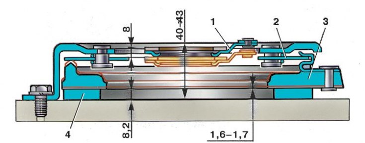
1 - thrust flange of the pressure spring; 2 - pressure diaphragm spring; 3 – pressure disk; 4 - ring
The control is carried out on a base that imitates the engine flywheel and has a metal intermediate ring 4 8.2 mm thick, replacing the driven disk (see fig. Clutch control).
1. After attaching the clutch cover, perform four disengagement strokes, applying a load of not more than 1372 N (140 kgf) on the thrust flange of the pressure spring. An opening stroke of 8 mm must correspond to a movement of the pressure plate by 1.6–1.7 mm (the smallest allowable - 1.4 mm).
2. The distance from the base to the working surface of the friction ring of the thrust flange should be 40–43 mm. In the course of work, due to the wear of the friction surfaces of the clutch discs, this size increases. If it reaches 48 mm or the movement of the pressure plate is less than 1.4 mm, replace the clutch cover assembly with the pressure plate.
3. Replace the friction linings of the driven disk if cracks appear, the distance between the rivet and the working surface decreases to 0.2 mm, and also if one-sided scuffing occurs.
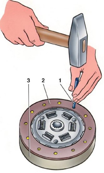
4. When repairing a driven disk (2) and replacement of friction linings, use mandrel 67.7851.9500 (1), conductor 67.7822.9517 (3) and equipment 67.7813.9503.
5. Flared rivets must not be broken.
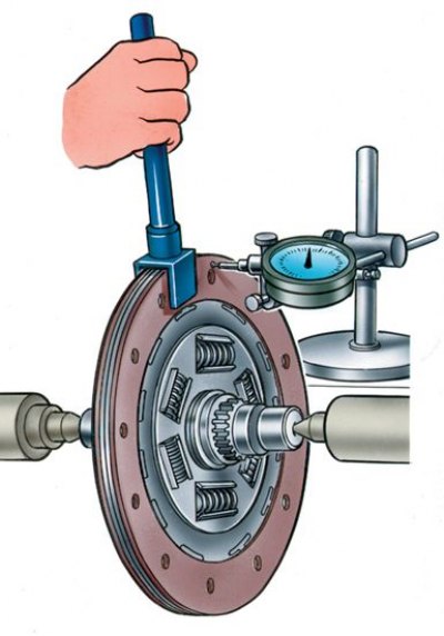
6. The runout of the working surface of the friction linings should not exceed 0.5 mm. If it is more, then straighten the disk or replace it with a new one.
7. If cracks appear on the driven disk or damper springs, replace the driven disk assembly.