
Clutch pedal and master cylinder
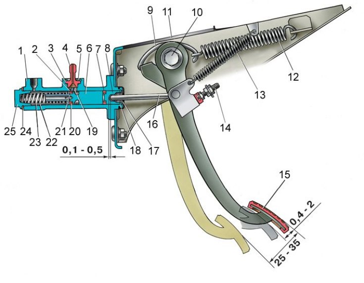
1 - the body of the main cylinder; 2 - bypass (compensatory) hole; 3 - fitting gasket; 4 - fitting; 5 - lock spring washer; 6 - piston of the main cylinder; 7 - sealing ring; 8 – pusher piston; 9 - hook; 10 - the axis of the pedals; 11 - bracket for clutch and brake pedals; 12 - clutch pedal servo spring; 13 – withdrawal spring of the clutch pedal; 14 - clutch pedal stroke limiter; 15 – clutch pedal; 16 - piston pusher; 17 - protective cap; 18 - retaining ring; 19 - inlet; 20 - sealing ring (ring valve); 21 - piston bypass hole; 22 - working cavity of the cylinder; 23 - spring; 24 - gasket; 25 - cork
1. A gap of 0.1–0.5 mm is set between the pusher and the master cylinder piston (see fig. Clutch pedal and master cylinder). This gap, necessary for the complete disengagement of the clutch, is regulated by the limiter 14 of the clutch pedal. The gap is determined by the free play of the pedal, equal to 0.4–2 mm.
2. The free travel of the pusher of the clutch release fork, equal to 4–5 mm, is regulated by the nut 5 (see fig. Slave cylinder and clutch release fork), which is fixed with a lock nut 6.
3. The amount of free travel of the pusher is controlled by a special template.
4. After making the above adjustments, the clutch pedal free play before the clutch is disengaged should be 25–35 mm.