
Elastic coupling connecting the cardan shaft with the gearbox
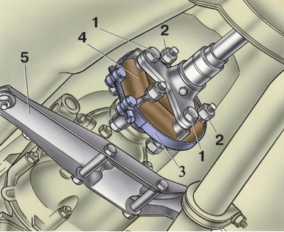
1 - bolts for fastening the cardan shaft flange to the elastic coupling; 2 – nuts of bolts of fastening of a flange of a secondary shaft of a transmission to an elastic coupling; 3 - fixture A.70025; 4 - elastic coupling; 5 - cross member rear engine mount
Removing
1. Position the vehicle over a pit or on a lift, chock the front wheels and hang the rear axle on one or both sides.
2. Release the parking brake and place the shift lever in neutral.
3. Disconnect the wires from the battery.
4. Remove the front floor mat and shift lever outer boot, then remove the plastic cover and seal.
5. Press down on rod 32 (see fig. Transmission) lever and with a screwdriver or some other pointed tool, remove the locking sleeve 36 from the groove on the lever stem and remove the stem.
6. Disconnect the suspension pipes and mufflers at the rear of the vehicle, and then the muffler pipe from the exhaust pipe.
7. Disconnect the clamp securing the intake pipe to the gearbox.
8. Using the wrench 02.7812.9500, unscrew the nuts securing the intake pipe of the mufflers to the exhaust manifold and remove the pipe down.
9. Loosen the lower clutch housing cover bolts.
10. Disconnect the connection wire from "weight" from the clutch housing and wires from the reversing light switch.
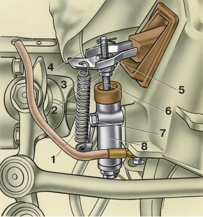
11. Unhook the release spring 1 from the clutch release fork 5 and remove the cotter pin 4 from the pusher 6. Disconnect the working cylinder 8 from the clutch housing. At the same time, cylinder 8, connected to the pipeline going to the master cylinder of the clutch release actuator, remains on the vehicle, which eliminates the loss of brake fluid and the need for subsequent bleeding of the hydraulic clutch release actuator (2 - locknut, 3 - thrust adjusting nut, 7 - bolt for securing the working cylinder to the clutch housing).
12. Remove the propeller shaft safety bracket. Disconnect the speedometer flexible shaft from the speedometer drive.
13. Put on the elastic sleeve 4 (see fig. Elastic coupling connecting the cardan shaft with the gearbox) clamp A.70025 and tighten it. This will facilitate the removal and subsequent installation of the flexible coupling.
14. Unscrew nuts 2 and, turning the cardan shaft, remove the bolts securing the flexible coupling 4 to the flange of the output shaft of the gearbox (see fig. Elastic coupling connecting the cardan shaft with the gearbox). Lower and move aside the front driveshaft with clutch.
15. Unscrew the swivel wrench 02.7812.9500 the bolts securing the starter to the clutch housing and remove it.
16. Loosen the clutch housing cover bolts.
17. Detach the engine rear mount from the cross member, and then remove the cross member while supporting the gearbox from below.
18. Place a special support on the hydraulic lift under the gearbox housing. Using a socket wrench A.55035, unscrew the mounting bolts and remove the gearbox together with the clutch housing, shifting it to the rear of the car so as to remove the gearbox input shaft from the front bearing and from the hub of the clutch disc.
Installation
19. The gearbox is installed in the reverse order of removal.
20. Apply a thin layer of LSTs-15 grease before installation (LITOL-24) on the splined end of the input shaft and center the clutch disc with the mandrel A.70081 (see fig. Centering the clutch disc using mandrel A.70081).