




Contents: Removal ↓ Installation ↓
Removal
Place the vehicle over an inspection pit or on a lift, place chocks under the front wheels and lift the rear axle on one or both sides. Release the parking brake and set the gearshift lever to neutral. Disconnect the cables from the battery.
Remove the front floor mat and outer covers from the transfer case and gearbox levers. Remove the lever hatch covers and seals. Unscrew the handles from the transfer case levers.
Press down on rod 27 (fig. 3-12) lever and using a screwdriver or some other pointed tool, remove the locking sleeve 31 from the groove on the lever rod; remove the rod.
Disconnect the pipe and muffler hanger at the rear of the car, then the muffler pipe from the intake pipe. Disconnect the clamp securing the exhaust pipe to the exhaust manifold and remove the pipe downwards.
Remove the lower clutch housing cover mounting bolts. Disconnect the ground wire from the clutch housing and the wires from the light switch.
Unhook the release spring 1 (Fig. 3-13) from the clutch release fork 5 and remove the cotter pin 4 from the pusher 6. Disconnect the slave cylinder 8 from the clutch housing. In this case, the cylinder 8, connected to the pipeline leading to the master cylinder of the clutch release drive, remains on the vehicle, which eliminates the loss of brake fluid and the need for subsequent bleeding of the hydraulic clutch release drive.
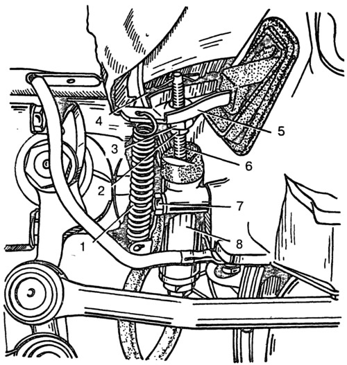
Fig. 3-13. Clutch release drive:
1 - fork release spring; 2 - lock nut; 3 - adjusting nut; 4 - cotter pin; 5 - clutch release fork; 6 - pusher; 7 - working cylinder mounting bolt; 8 - clutch release drive slave cylinder.
Place clamp 2 (A.70025) on elastic coupling 3 (Fig. 3-14) and tighten it. This will facilitate removal and subsequent installation of the elastic coupling. Unscrew nuts 1 and, turning the intermediate cardan shaft, remove the bolts securing elastic coupling 3 to the flange of the secondary shaft of the gearbox.
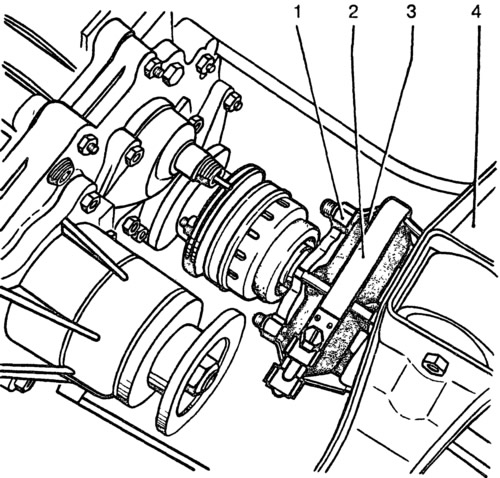
Fig. 3-14. Flexible coupling connecting the cardan shaft to the gearbox:
1 - nuts for fastening the flange of the cardan shaft to the elastic coupling; 2 - clamp A.70025; 3 - elastic coupling; 4 - rear engine mount cross member.
Disconnect the speedometer flexible shaft from the speedometer drive on the transfer case.
Disconnect the flanges of the cardan shafts of the front and rear axle drives from the flanges of the transfer case shafts. Lower and move aside the cardan shafts of the axle drives.
Loosen the bolts securing the transfer case brackets to the body and remove it together with the propeller shaft.
Loosen the bolts securing the starter to the clutch housing using the 02.7812.9500 socket wrench and release it. Loosen the bolts securing the clutch housing cover.
Disconnect the rear engine mount support from crossmember 4 (Fig. 3-14), and then remove the crossmember while supporting the gearbox from below.
Place a jack, stand or other suitable support under the gearbox housing. Using the A.55035 socket wrench, loosen the mounting bolts and remove the gearbox together with the clutch housing, moving it toward the rear of the vehicle so as to remove the gearbox input shaft from the front bearing and from the driven disk hub.
Warning: When removing or installing the gearbox, do not rest the end of the input shaft on the thrust flange of the clutch pressure spring to avoid deforming the clutch connecting plates.
[The information is posted on the portal vazbook.ru]
Installation
The gearbox is installed in the reverse order of removal. Before installation, apply a thin layer of LSC-15 or Litol-24 grease to the splined end of the primary shaft and center the driven clutch disc with the A.70081 mandrel (fig. 3-4).