




Contents: Disassembly ↓ Assembly ↓
Rear of the five-speed gearbox
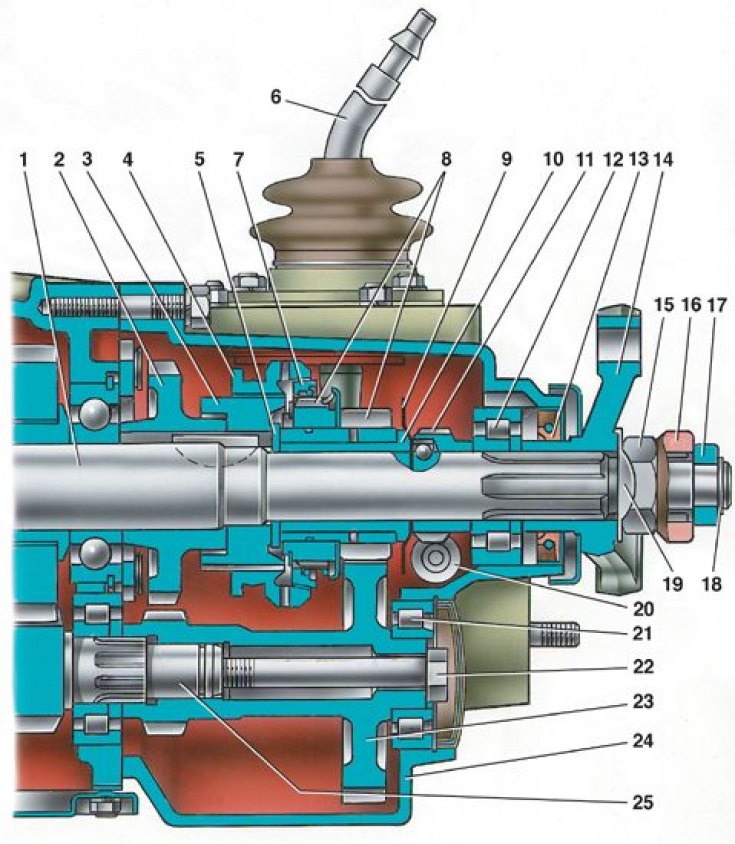
1 – secondary shaft; 2 – reverse driven gear; 3 – hub of the 5th gear synchronizer clutch; 4 – synchronizer clutch; 5 – washer; 6 – gear shift lever; 7 – synchronizer locking ring; 8 – gear and toothed ring of the 5th gear synchronizer; 9 – oil deflector washer; 10 – V gear sleeve; 11 – speedometer drive pinion; 12 – secondary shaft rear bearing; 13 – oil seal; 14 – elastic coupling flange; 1 5 – nut; 16 – centering ring seal; 17 – centering ring; 18 – retaining ring; 19 – lock washer; 20 – driven gear of the speedometer drive; 21 – gear block bearing; 22 – gear block mounting bolt; 23 – block of gears of the 5th gear and reverse gear; 24 – rear cover of the gearbox; 25 – intermediate shaft
Unscrewing the bolts securing the gear block and the fork for engaging the 5th gear and reverse gear
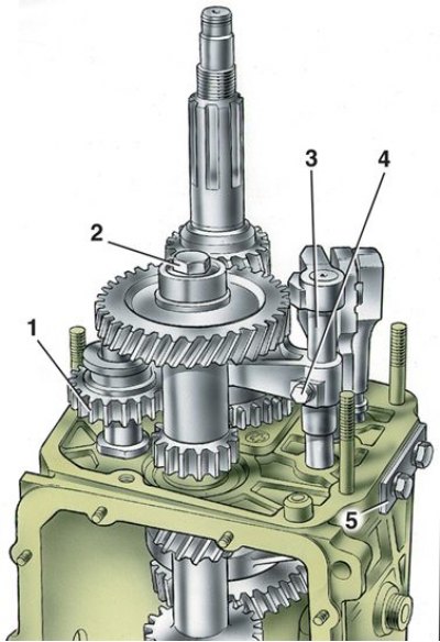
1 – intermediate reverse gear; 2 – gear block mounting bolt; 3 – fork stem; 4 – fork mounting bolt; 5 – cover of the clamps
Removal the reverse driven gear and the hub of the 5th gear synchronizer clutch
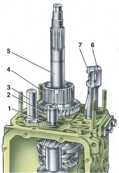
1 – intermediate shaft; 2 – reverse driven gear; 3 – reverse intermediate gear axle; 4 – hub of the 5th gear synchronizer clutch; 5 – secondary shaft; 6 – rod for engaging the 1st and 2nd gears; 7 – fork rod for engaging III and IV gears
Gear selection mechanism
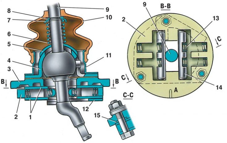
1 – guide plate washers; 2 – gear shift lever guide plate; 3 – gear shift lever housing; 4 – ball joint of the lever; 5 – spherical washer; 6 – spring; 7 – thrust ring; 8 – retaining ring; 9 – gear shift lever; 10 – protective cover; 11 – flange; 12 – reverse locking plate; 13 – spring; 14 – guide bar; 15 – sealing ring; A - risk
Removal the intermediate reverse gear, the V gear assembly with the synchronizer and fork
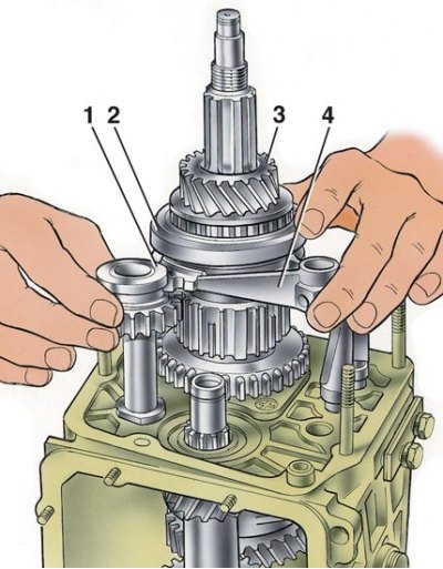
1 – intermediate reverse gear; 2 – 5th gear engagement clutch; 3 – V-gear gear assembly with synchronizer; 4 – fork for engaging 5th gear and reverse gear
Disassembly
1. Before removing the rear cover, set the gear shift lever to neutral position, unscrew the nuts securing the gear selection mechanism assembly with the mechanism.
2. Then unfasten the rear cover mounting nuts and remove it. One of the cover mounting nuts is unscrewed from inside the gearbox housing with the lower cover removed.
3. When removing the rear cover, it is necessary to not only push it back, but also turn it to prevent it from touching the reverse gear block and fifth gear.
[The article is copied from the website: www.VAZbook.ru]
4. After removing the inner ring of the rear bearing from the secondary shaft 12 (see Fig. Rear of the five-speed gearbox) and the speedometer drive pinion, loosen the cover mounting bolts 5 (see fig. Unscrewing the bolts securing the gear block and the fork for engaging the 5th gear and reverse gear) clamps and unscrew bolts 2 and 4 securing the gear block and the fifth gear and reverse gear engagement fork.
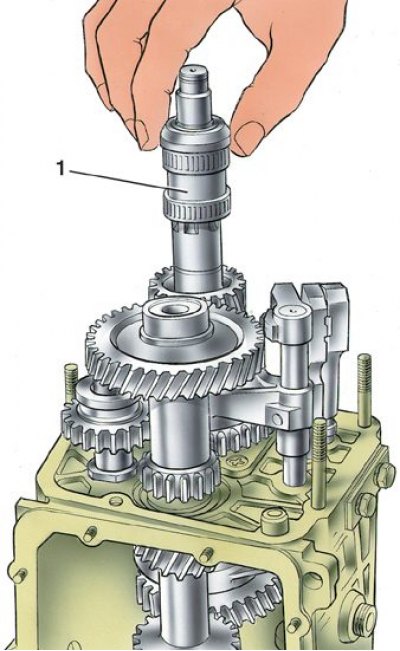
5. Remove the oil deflector washer 9 (see Fig. Rear of the five-speed gearbox) and then sleeve 1 of the fifth gear.
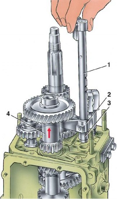
6. Remove rod 1 from fork 2. At the same time, remove spacer sleeve 3 from the rod. Then remove gear block 4 from the splines of the intermediate shaft.
7. Remove the 1st reverse intermediate gear from the axle at the same time (see fig. Removing the intermediate reverse gear, the 5th gear assembly with the synchronizer and fork), gear 3 assembled with clutch 2 and fork 4 from the secondary shaft.
8. Remove washer 5 from the secondary shaft (see Fig. Rear of the five-speed gearbox).
9. Then, using a screwdriver-type mandrel, remove the hub 4 from the key (see fig. Removing the reverse driven gear and the hub of the 5th gear synchronizer clutch) synchronizer of the fifth gear and driven gear 2 of the reverse gear.
10. Carry out further disassembly of the gearbox in the order described for the four-speed gearbox.
11. If necessary, disassemble the lever and gear selection mechanism by removing the protective cover 10 (see fig. Gear selection mechanism), retaining and thrust rings 7 and 8, spring and spherical washer 5 from the gear shift lever.
12. Visually mark the position of the parts relative to mark A on the guide plate so that the parts are connected in the same position during assembly.
13. After unscrewing the nuts from the mounting bolts, separate the parts of the gear selection mechanism and remove the lever 9, its ball joint 4 and rubber sealing rings 15.
Assembly
1. Assembly of the fifth stage, reverse gear and gear selection mechanism is carried out in the reverse order of disassembly, taking into account the following.
2. Fasten the reverse intermediate gear shaft before installing the shafts in the gearbox housing with a torque of 78 N·m (8 kgf·m).
3. Before installing the fifth gear and reverse gear fork rod into the crankcase, install a spacer sleeve on it.
4. Press the inner bearing ring onto the fifth gear and reverse gear block, and the outer bearing ring into the rear cover socket.
5. Press the secondary shaft rear bearing onto the shaft to facilitate installation of the rear cover.
6. Reverse intermediate gear 1, gear 3 and fork 4 (see fig. Removing the intermediate reverse gear, the 5th gear assembly with the synchronizer and fork) install simultaneously.
7. When assembling the gear shift lever, coat the ball head or ball joint sphere with LSC-15 grease.
8. Tighten the gear block mounting bolt to a torque of 78 N·m (8 kgf·m).