
In the bottom heads...
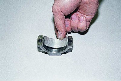
... and the connecting rod caps are fitted with steel-aluminum liners.
They are kept from turning by the locks included in the slots of the beds.
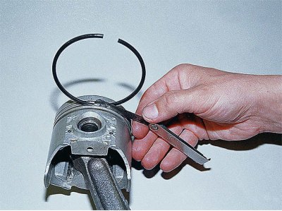
We clamp the connecting rod in a vise and, unclenching, remove the upper...
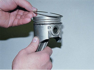
...and lower compression rings. When they are subsequently installed, the label «TOP» or «TOR» should point towards the piston crown.
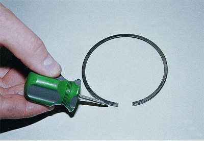
The ring may not be inscribed, but the lower compression ring is always installed chamfered down.
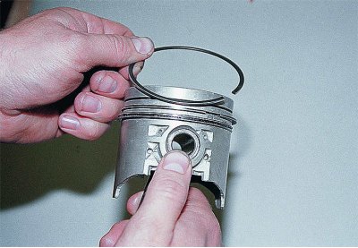
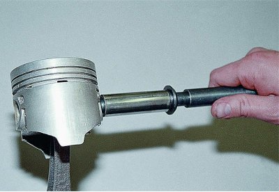
Removing the oil ring...
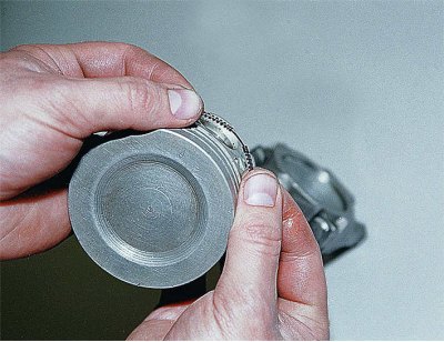
...with an extension.
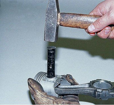
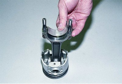
By installing the piston on a wooden mandrel with a hole or holding it on weight, we knock out the finger.
We assemble the connecting rod and piston group in the reverse order.
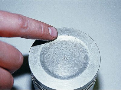
We select a new piston. The piston class is indicated by a letter, and the pin category by a number (see mating parts table).
The clearance between the piston and cylinder for new parts is 0.05–0.07 mm. When worn, the maximum allowable clearance is 0.15 mm.
Properly selected, lubricated with engine oil, the finger should enter the piston holes under the force of the thumb and not fall out of the piston in a vertical position.
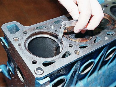
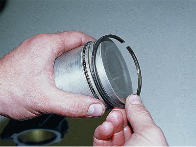
Having installed the ring in the cylinder, we check the gap in its lock with a set of probes. It should be 0.25–0.40 mm for all rings. If the clearance is too high, the rings must be replaced.
We also check the gap between the ring and the piston groove with a set of feelers. For the upper compression ring, it should be 0.045-0.077, the lower one - 0.025-0.057, the oil scraper - 0.020-0.052 mm. The maximum allowable wear clearance is 0.15 mm.
We install rings in the piston grooves, then orient them as follows:
- we orient the lock of the upper compression ring at an angle of 45°to the axis of the piston pin;
- we turn the lock of the lower compression ring relative to the lock of the upper ring in the opposite direction;
- we set the lock of the oil scraper ring at 90°relative to the locks of other rings. In this case, the joint of its expander should be on the opposite side of the lock of the ring itself.
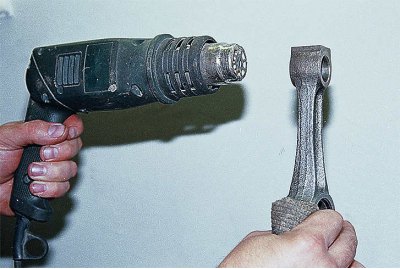
We heat the upper head of the connecting rod to 240°C, holding it in a vice.
The finger can be pre-cooled in the freezer.
We put a piston on the connecting rod and quickly press in the finger with the help of a mandrel.
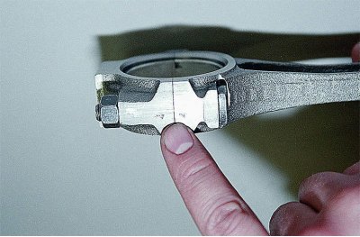
The numbers on the connecting rod and its cap indicating the cylinder number must be on the same side and match.
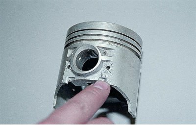
Label «P» on the piston must point towards the front of the cylinder block.