
English Русский
Български
Беларускі
Український
Српски
Hrvatski
Română
Polski
Slovenský
Magyar
| Articles | Contacts | Sitemap |   
Repair and maintenance Lada Repair and maintenance Mazda Repair and maintenance Mitsubishi Repair and maintenance Toyota Repair and maintenance Land Rover Repair and maintenance Hyundai Repair and maintenance Nissan
VAZbook.ru


Main     1111   2101   2105   2106   2107   2109   2110   2115   2121  
VAZ-2121 (1977-1994) VAZ-21213 (1994-2006) VAZ-21214 (1994-2006)
  • Main
  • «Niva»
  • VAZ-21213
  • Power unit
  • Engine repair
  • Features of the connecting rod and piston group

Features of the connecting rod and piston group (VAZ-21213)

            0

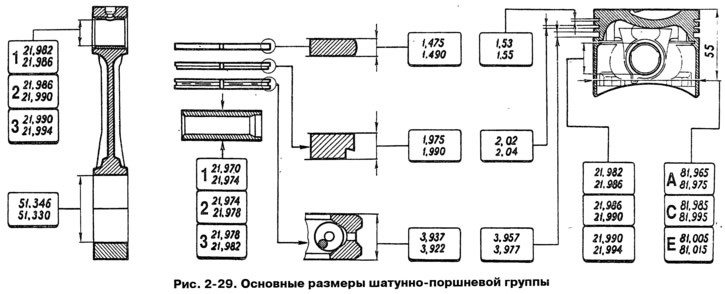
The main dimensions of the connecting rod and piston group are given in Fig. 2-29.

The main dimensions of the connecting rod and piston group are given in Fig. 2-29.


Piston - aluminum casting. During manufacturing, the piston weight is strictly maintained. Therefore, when assembling the engine, it is not necessary to select pistons of the same group by weight.

According to the outer diameter, pistons are divided into five classes (A, B, C, D, E) through 0.01 mm. The outer surface of the piston has a complex shape. It is conical in height and oval in cross-section. Therefore, it is necessary to measure the piston diameter only in the plane perpendicular to the piston pin, at a distance of 55 mm from the piston bottom.

According to the diameter of the hole for the piston pin, pistons are divided into three classes (1, 2, 3) through 0.004 mm. The classes of piston diameters and holes for the piston pin are stamped on the piston bottom (Fig. 2-30).
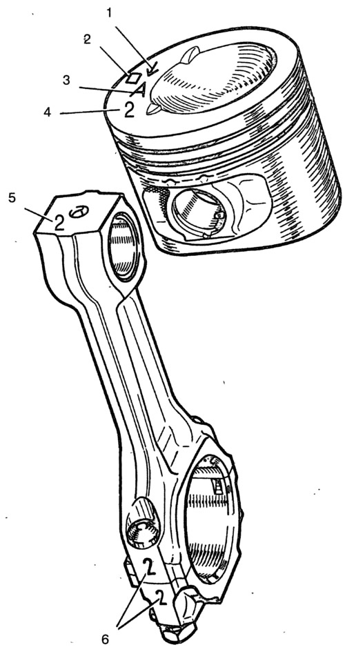
Fig. 2-30. Piston and connecting rod markings:

Fig. 2-30. Piston and connecting rod markings:
1 - arrow for orienting the piston in the cylinder; 2 - repair size; 3 - piston class; 4 - piston pin bore class; 5 - class of connecting rod by piston pin bore; 6 - cylinder number.


Pistons of repair sizes are manufactured with an outer diameter increased by 0.4 and 0.8 mm. The bottoms of these pistons are marked with a triangle or square. The triangle corresponds to an increase in the outer diameter by 0.4 mm, and the square - by 0.8 mm.

The arrow on the piston bottom shows how to correctly orient the piston when installing it in the cylinder. It should be directed towards the camshaft drive.

Piston pin - steel, hollow, floating type, i.e. freely rotates in the piston bosses and connecting rod bushing. The pin is fixed in the piston by two steel retaining rings.

According to the outer diameter, the pins are divided into three classes, each with a 0.004 mm interval. The class is marked with paint on the end of the pin: blue mark - first, green - second, and red - third class.

Piston rings - made of cast iron. Upper compression ring - with chrome-plated barrel-shaped outer surface. Lower compression ring of scraper type. Oil scraper ring - with chrome-plated working edges and with expansion coil spring (expander).

On rings of repair sizes, the digital marking "40" or "80" is placed, which corresponds to an increase in the outer diameter by 0.4 or 0.8 mm.

Connecting rod - steel, forged. It is processed together with the cover, and therefore they are not interchangeable separately. In order not to mix up the covers and connecting rods during assembly, they are stamped with number 6 (Fig. 2-30) of the cylinder in which they are installed. During assembly, the numbers on the connecting rod and cover must be on the same side.


A steel-bronze bushing is pressed into the upper head of the connecting rod. According to the diameter of the hole in this bushing, the connecting rods are divided into three classes, each 0.004 mm (the same as pistons). Class 5 number is stamped on the upper head of the connecting rod.

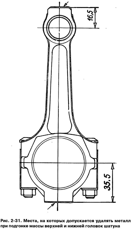
By the weight of the upper and lower heads, connecting rods are divided into classes (Table 2-1), marked with paint on the connecting rod rod. Connecting rods of the same weight class must be installed on the engine. The weight of the connecting rods can be adjusted by removing metal from the bosses on the heads to the minimum dimensions of 16.5 and 35.5 mm (Fig. 2-31).
By the weight of the upper and lower heads, connecting rods are divided into classes (Table 2-1),…


Table 2-1. Connecting rod classes by weight of upper and lower heads
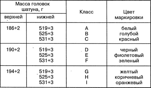


Table 2-1. Connecting rod classes by weight of upper and lower heads


This article is available at russian, bulgarian, belarusian, ukrainian, serbian, croatian, romanian, polish, slovak, hungarian
The text was reviewed by the specialist: Grigory Vologodtsev

Share with friends:

Previous articles
VAZ-21213: Engine repair
Next articles

Checking the technical condition and repairing the cylinder block
Features of the cylinder block device
Checking the engine on a car after repair
Engine running-in after repair
Engine assembly
Selecting a piston for a cylinder
Disassembly and assembly of the connecting rod and piston group
Checking the technical condition of the connecting rod and piston group
Features of the crankshaft and flywheel
Checking the technical condition and repairing the crankshaft and flywheel

More articles from other manuals on VAZ cars:
➠ Removal and installation of the connecting rod and piston group VAZ-1111 (1988-1996)
➠ Assembly of the connecting rod and piston group VAZ-21011 (1974-1983)
➠ Construction of the connecting rod and piston group VAZ-2105 (1979-2010)
➠ Connecting rod and piston group — removal and installation VAZ-2108 (1984-2003)
➠ Replacing the connecting rod and piston group with a floating pin VAZ-2112 (1999-2007)
Link in different formats to this page


Visitor comments

No comments yet


How much will 24 + 47 ?


VAZ-2121 (1977-1994) 
  • General information
  • Vehicle device
  • Car VAZ-21219
  • Power unit
  • Engine repair
  • Cooling system
  • Lubrication system
  • Supply system
  • Transmission
  • Clutch
  • Car gearbox
  • Transfer case
  • Cardan gear
  • Rear axle and gearbox
  • Front axle
  • Chassis
  • Front suspension
  • Rear suspension
  • Steering
  • Brake system
  • Body
  • Exterior
  • Interior
  • Doors and windows
  • Electrical equipment
  • Equipment and devices
  • Headlights and lighting
  • Engine electrics


VAZ-21213 (1994-2006) 
  • General information
  • Vehicle device
  • User manual
  • Power unit
  • Engine repair
  • Cooling and lubrication system
  • Supply system
  • Transmission
  • Clutch
  • Car gearbox
  • Transfer case
  • Cardan gear
  • Rear axle and shafts
  • Front axle and wheel drive
  • Chassis
  • Wheel suspension
  • Steering
  • Brake system
  • Body
  • Exterior
  • Interior
  • Electrical equipment
  • Engine electrics
  • Equipment and devices


VAZ-21214 (1994-2006) 
  • General information
  • Vehicle information
  • Troubleshooting
  • Power unit
  • Engine repair
  • Cooling system
  • Fuel system (carburetor)
  • Fuel system (injector)
  • Ignition system
  • Control system
  • Exhaust system
  • Transmission
  • Clutch
  • Car gearbox
  • Transfer case
  • Cardan gear
  • Front axle
  • Rear axle
  • Chassis
  • Front suspension
  • Rear suspension
  • Steering
  • Brake system
  • Body
  • Exterior
  • Interior
  • Doors, covers and windows
  • Ventilation and heating
  • Electrical equipment
  • Equipment and devices
  • Headlights and lighting
  • Engine electrics
  • Electrical circuits


VAZbook.ru © 2017 · Mobile version · Contact with administration · Sitemap: EN BG BY UA RS HR RO PL SK HU · Site search · News and articles VAZ-1111 · VAZ-11113 · VAZ-2101 · VAZ-21011 · VAZ-2104 · VAZ-2105 · VAZ-21051 · VAZ-2106 · VAZ-21061 · VAZ-2107 · VAZ-21099 · VAZ-2109 · VAZ-2108 · VAZ-2110 · VAZ-2112 · VAZ-2114 · VAZ-2115 · VAZ-2121 · VAZ-21213 · VAZ-21214 ·
The site stores technical data using cookies to improve the service.