
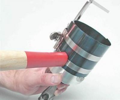
- mandrel for crimping piston rings;
- torque wrench.
Removing
1. Remove the cylinder head (see "Cylinder head - removal and installation").
2. Remove the engine oil pan (see "Engine oil pan - gasket replacement").
3. Remove the oil pickup (see "Oil intake - removal and installation").
4. We wrap in place the bolt of the crankshaft pulley and, with a key by 17 mm (on car parts by 19 mm) turning the crankshaft clockwise, set the piston of the first cylinder to the lower position.
Tip: When loosening the nuts on the connecting rod caps, you can accidentally damage the oil level sensor, so it is advisable to remove it (see "Low oil level sensor - check and replace").
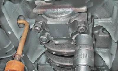
5. socket wrench by 14 mm unscrew the two nuts securing the connecting rod cover of the first cylinder.
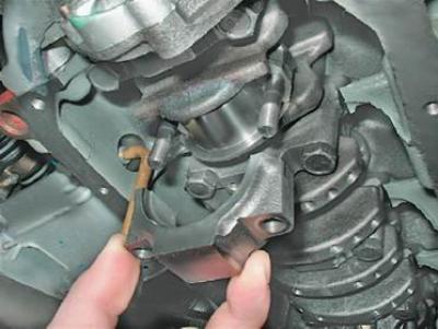
6. Remove the connecting rod cover.
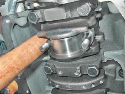
7. Having rested the hammer handle on the connecting rod, we push it up.
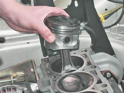
8. Remove the piston assembly with the connecting rod from the cylinder.
9. We take out loose leaves from a rod and its cover.
Warning! When disassembling the connecting rod, do not press the bolts out of it.
10. Clamp the piston by the connecting rod in a vice.
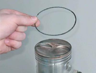
11. Slightly spreading the lock of the ring, remove the upper compression ring.
12. Similarly, remove the lower compression ring.
13. Remove the oil scraper ring...
...and its expander.
Warning! The expediency of replacing the rings depends on the degree of wear of the cylinders (see "Piston and connecting rod - replacement").
Installation
1. Thoroughly clean the piston from carbon deposits and deposits. We examine the piston and connecting rod. Cracks are unacceptable.
2. We select new rings in accordance with the piston diameter - nominal or repair size. There are no markings on the rings of the nominal size, the repair rings are increased in diameter by 0.4 or 0.8 mm, and are marked "40" And "80" respectively.
3. Before installing new rings with a set of probes, we measure the gap between the piston ring and the wall of the groove into which the ring will be installed.
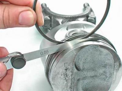
If the gap exceeds the maximum allowable, the piston must be replaced.
Table 8.1.4. Permissible clearances between groove walls and piston rings
| Ring | Gap, mm |
| Top compression ring | 0,04-0,07 |
| Lower compression ring | 0,03-0,06 |
| Oil scraper ring | 0,02-0,05 |
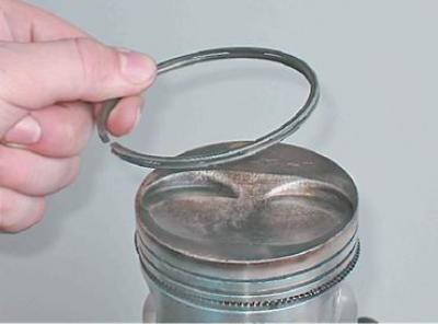
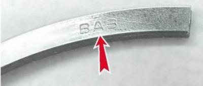
Oil ring...
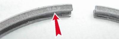
... and install the upper compression ring with the inscription "VAZ" or "TOR" up.
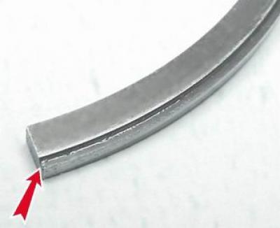
We orient the lower compression ring in such a way that it is directed downwards with a groove.
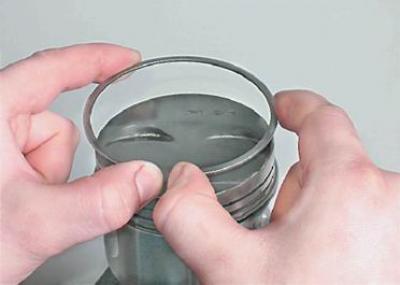
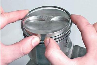
4. We put the rings on the piston as follows: pushing the ring lock (no more than is required to put the ring on the piston), we start the lock on the piston first, and then the back of the ring.
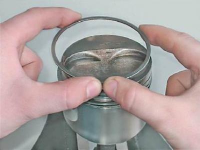
We install new rings on the piston, starting with the oil scraper ring expander. After installing the oil scraper ring, the expander lock must be rotated 180°relative to the ring lock.
After installing the rings on the piston, we turn them with locks so that the lock of the upper compression ring is located at an angle of 45°to the axis of the piston pin, the lock of the lower compression ring is turned 180°, and the lock of the oil scraper ring is 90°relative to the lock of the upper compression ring.
5. Lubricate the piston, rings and the inner surface of the cylinder with clean engine oil.
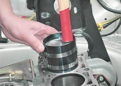
6. We put the mandrel on the piston and crimp the rings with it, periodically tapping the mandrel for self-alignment of the rings with the hammer handle.
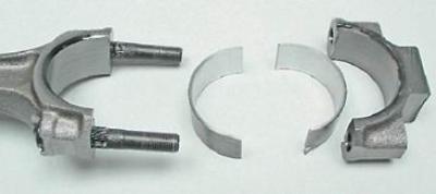
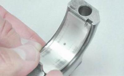
7. We wipe dry the installation sites of the liners in the connecting rod and the cover and install the liners in the lower head of the connecting rod.
8. Lubricate the inner surfaces of the liners and the connecting rod neck of the crankshaft with clean engine oil. By turning the crankshaft, we move the neck to the lowest position.
9. We install the piston on the block and orient it so that the arrow on the piston bottom is directed towards the crankshaft pulley (see "Piston rings and connecting rod bearings - replacement").
10. Pressing the mandrel against the block and tapping the piston bottom with the hammer handle, we sink it into the cylinder, while simultaneously monitoring the progress of the connecting rod to the crankshaft journal.
11. We install the cover assembly with the insert on the connecting rod and tighten the nuts for its fastening to a torque of 43.3-53.5 N·m (4.4-5.5 kgf·m).
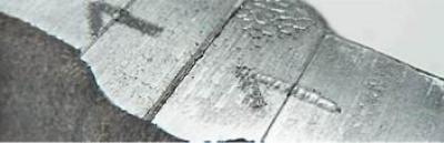
Warning! The connecting rod caps are not interchangeable. The connecting rod and its cap are marked with the number of the cylinder in which the connecting rod is to be installed. On the assembled connecting rod, the numbers should be located on one side.
We replace the rings of the other three pistons in the same way.
After installing all the pistons, we assemble the engine in the reverse order of disassembly.