

The main engine that is installed on most cars is 2108. Therefore, later in the book the structure of this engine is described and features are given (if they are) units and parts of engines 21081 and 21083.
Engine 2108 - four-stroke carbureted four-cylinder in-line vertical arrangement of cylinders and an overhead camshaft. The engine is specially designed for a transverse arrangement on a front-wheel drive vehicle. Therefore, it is maximally compressed in length and its layout and main dimensions are chosen so that it, together with the gearbox, can be placed transversely between the mudguards of the front wheels.
When developing the engine, special attention was paid to reducing its weight and improving efficiency, as well as meeting environmental requirements - reducing exhaust gas toxicity. Good weight performance (92 kg for engine 2108 and 95 kg for 21083) managed to be obtained due to the rational layout of the engine and the use of new design solutions: the installation of an original oil pump with direct drive from the crankshaft, a compact valve drive, etc.
The solution to a complex problem - improving efficiency and at the same time achieving maximum engine power was obtained through many measures. Here and the improvement of the shape of the combustion chamber with high (9,9) compression ratio, and the selection of valve timing, camshaft profile, and finding a new design of the carburetor and ignition devices with the most advantageous adjustments.
Complete with gearbox (pic. 8) and clutch (located in crankcase 3) engine 4 forms a single rigid unit - the power unit. Such a design solution simplifies the process of conveyor assembly of the car, since the power unit can be assembled separately, and then assembled on the car.
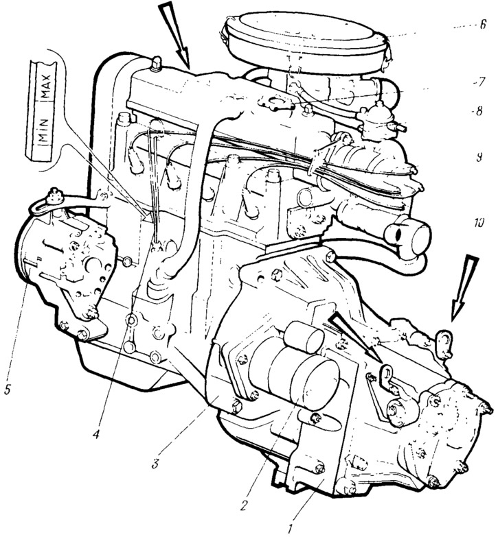
Pic. 8. Power unit (the arrows show the brackets for slinging the power unit):
1 - gearbox; 2 - starter; 3 - clutch housing; 4 - engine; 5 - generator; 6 - air filter; 7 - oil filler cap; 8 - fuel pump; 9 - sensor-distributor ignition; 10 - thermostat.
All engine components that require maintenance during vehicle operation are located in an easily accessible area: on top or on the left side of the engine, which, due to its transverse location on the vehicle, is front. On the left are the spark plugs, alternator 5, starter 2 and oil dipstick. Air filter 6 and ignition distribution sensor 9 are located on top. Fuel pump 8 is also installed at the top, but on the right side of the engine (rear, when viewed in the direction of the car). This arrangement of the fuel pump reduces the risk of fires in an accident due to damaged fuel lines.
The engine cylinders are combined with the upper part of the crankcase and represent a single casting - cylinder block 3 (pic. 9). With this arrangement, strength, rigidity and compactness of the structure are ensured, and the mass of the engine is reduced. From below, the cylinder block is closed with a steel stamped crankcase sump 1, which also serves as a container for oil. Between the pan and the cylinder block is a cork-rubber gasket.
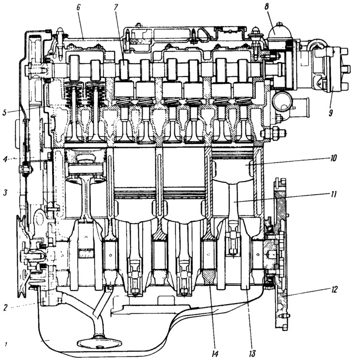
Pic. 9. Longitudinal section of the engine:
1 - crankcase; 2 - oil pump; 3 - cylinder block; 4 - camshaft drive belt; 5 - cylinder head; 6 - cylinder head cover; 7 - camshaft; 8 - fuel pump; 9 - sensor-distributor ignition; 10 - piston; 11 - connecting rod; 12 - flywheel; 13 - crankshaft; 14 - main bearing cap.
On top of the cylinder block, an aluminum head 5 common to four cylinders is installed, in which the combustion chambers, valve mechanism and gas channels are located. A sealing metal-asbestos gasket is located between the head and the cylinder block. Each cylinder has one intake and one exhaust valve, which are actuated by a camshaft mounted on the cylinder head. The top location of the camshaft makes it possible to reduce the mass of reciprocating moving parts and thereby ensure high reliability of the gas distribution mechanism at a high engine speed.
The camshaft 7 is driven from the crankshaft by a special toothed belt with an eccentric roller tensioner. The advantages of such a drive are the simplicity of design, lower weight compared to other types of gears and reduced engine noise. The belt drive is closed at the front with a plastic cover and at the back with a steel cover.
Crankshaft 13 cast iron five-bearing. Such a shaft is cheaper than forged and more durable in operation. Five pillars ensure its high rigidity. It bends less and creates better conditions for the operation of bearings. Large journal diameters (51 mm - main and 48 mm - connecting rod) allow to reduce the load on the bearings, thereby reducing the wear of the necks and bearing shells, increasing the durability of the crankshaft. The ends of the crankshaft are sealed with self-clamping rubber seals.
Pistons 10 aluminum cast, have two compression rings and one oil scraper. The piston pin is pressed into the upper head of the connecting rod and can rotate freely in the piston bosses. Connecting rods 11 - forged steel.
Engine lubrication system - combined (under pressure and spray). Under pressure, the main and connecting rod bearings of the crankshaft, camshaft bearings are lubricated. A distinctive feature of the lubrication system is the original oil pump with internal gears. The pump drive is carried out directly from the crankshaft, at the front end of which the pump drive gear is installed. Oil filter 2 (pic. 10) with a filter element made of special cardboard, full-flow, i.e., all the oil going to lubricate the engine passes through the filter. The oil used for engine lubrication has a complex of additives that give the oil high lubricating properties, oxidation resistance, and allow operation in a wide temperature range.
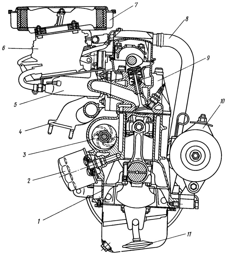
Fig 10. Cross section of the engine:
1 - cylinder block; 2 - oil filter; 3 coolant pump; 4 exhaust manifold; 5 - inlet pipeline; 6 - carburetor; 7 - air filter; 8 - pipeline of the crankcase ventilation system; 9 - cylinder head; 10 generator; 11 - oil pump receiver.
The cooling system is liquid, closed type, filled with a special coolant that has anti-corrosion and anti-foaming additives and freezes only at low temperatures. The thermostat with a solid filler maintains a constant thermal regime of the engine. To reduce weight, the radiator has plastic tanks and an aluminum core. Air is blown through the radiator by a four-blade plastic electric fan. The system operates at higher thermal conditions than previous engines. The temperature of the beginning and full opening of the main valve of the thermostat is respectively 87 and 102°C. Coolant pump 3 is a centrifugal type, located directly in the cylinder block and rotates by the same belt drive as the camshaft.
The power system includes an air filter, fuel pump, fuel tank and carburetor. Air filter 7 - dry type, with a temperature regulator and with a replaceable filter element made of special cardboard with a nylon wool pre-cleaner.
The fuel pump is diaphragm, with a mesh filter and a lever for manual fuel pumping. To increase the reliability of the fuel supply, the fuel supply system provides for draining excess fuel from the carburetor back into the fuel tank. In addition, the power system has a fine filter and a gasoline vapor separator that prevents vapors from escaping into the atmosphere.
Carburetor 6 is a new design emulsion type, two-chamber, with a falling flow and sequential opening of throttle valves. It has a balanced float chamber, a system for exhausting crankcase gases behind the throttle valve, an economizer for power modes with a pneumatic drive, a diaphragm accelerator pump, an economizer for forced idling with electronic control that takes into account the crankshaft speed, a starting device with a pneumatic drive. The drive of the throttle and air dampers of the carburetor is cable.
The ignition system is electronic, non-contact, high energy. It provides reliable sparking at any crankshaft speed.
The engine as a whole has high reliability and durability. The use of a thin-walled cast-iron cylinder block, a five-bearing crankshaft with developed necks, steel-aluminum thin-walled crankshaft bearing shells provides at least 125,000 km of vehicle run before overhaul.