
Cylinder block
All engine cylinders, together with the upper part of the crankcase, are combined into a common unit - a cylinder block cast from special high-strength cast iron. This design allows, with a relatively small mass, to obtain high rigidity and strength, since the force from the pressure of gases in a separate cylinder is perceived by the entire section of the cylinder block. It well resists the action of inertial forces and moments that arise from the moving parts of the crank mechanism. To increase rigidity, the cylinder block has five baffles with ribs and an increased thickness of the top plate to which the cylinder head is attached.
Cylinders are located in the block vertically, in a row. They do not have any insert sleeves and are bored directly into the cylinder block. To obtain a high degree of surface finish, the cylinder walls are honed.
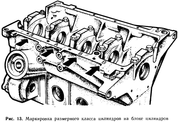
For normal engine operation, the clearance between the piston and cylinder must be within certain limits: 0.025... 0.045 mm on a new engine and not exceed 0.15 mm for worn pistons and cylinders. To make it easier to obtain such a clearance when assembling the engine, the diameters of the cylinders and pistons are divided through 0.01 mm into five classes, denoted by the Latin letters A, B, C, D, E (pic. 12). When assembling the engine, pistons of the same class are inserted into the cylinders of a certain class, which ensures that the specified clearance value is obtained. Class (letter) cylinder diameter is stamped on the bottom plane of the cylinder block against each cylinder (pic. 13).
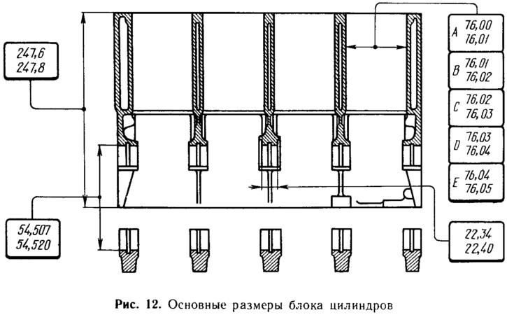
The main dimensions of the cylinder block of the 2108 engine are shown in fig. 12. The engine block 21081 differs from 2108 in a lower height - 242... 242.2 mm, and the cylinder block 21083 compared to 2108 has a larger cylinder diameter:
- A - 82.00... 82.01 mm
- B - 82.01... 82.02 mm
- C - 82.02... 82.03 mm
- D - 82.03...82.04 mm
- E - 82.04... 82.05 mm
The engine model number is cast on the top of the cylinder block on the left side.
The cylinder block is an expensive part. Therefore, in order to extend its service life, the possibility of repairing the cylinders is provided. The wall thickness allows cylinders to be bored and honed to fit piston repair sizes increased by 0.4 and 0.8 mm. Boring is performed if the wear of the cylinders exceeds 0.15 mm or if there are burrs on their walls.
In the lower part of the cylinder block there are five crankshaft main bearing supports, on which thin-walled steel-aluminum liners are placed. The holes of the supports are made half in the cylinder block, and half in the bearing caps. Each cover is attached to the cylinder block with two self-locking bolts. To ensure high accuracy, the bearing holes are finished together with the bearing caps. Therefore, the covers are not interchangeable: they cannot be interchanged and rearranged from one cylinder block to another. To distinguish main bearing caps on their outer side there is a marking in the form of scratches (pic. 14).

When assembling the engine, the bearing caps must be installed in a strictly defined position: in the same position in which they were in the cylinder block when machining holes in the bearings. Therefore, in order not to accidentally turn over the covers, they are made asymmetricahp respect to the sides of the cover, the axis of the half-hole in it is shifted by 1 mm to the left. Properly installed covers should have marks on the left side of the engine (the side where the alternator and starter are located).
Along the right side of the cylinder block, the main channel of the lubrication system is drilled. Five inclined channels depart from it to the main bearings of the crankshaft and a vertical channel for supplying oil up to the camshaft. On the right front side of the cylinder block there is a flange for installing an oil filter. Channels run from the flange to the main channel of the lubrication system and to the oil pump, which is attached to the front end of the cylinder block. On the left side of the block there is a tide with a hole for a fitting, to which a crankcase exhaust hose is attached. An oil level indicator is also inserted into this fitting.
The cylinder block cooling jacket is common to all cylinders. The coolant channels are made along the entire height of the cylinders, which improves the cooling of the pistons and piston rings and reduces block deformation from uneven heating. To fix the cooling jacket rods during the casting of the cylinder block, there are six holes in its outer walls, which are then closed with steel bowl-shaped plugs. Cooling jacket directly (without intermediate pipelines) connected to the coolant pump located in the tide on the right side of the cylinder block. The cooling jackets of the block and the cylinder head communicate through holes in the upper plane of the cylinder block.
On the left side on the cylinder block there are tides with holes for mounting the generator and the front suspension bracket of the power unit. On the right side, in addition to the flange for the oil filter, there is also a flange with four holes for mounting the cylinder block on the assembly stand. At the rear of the cylinder block are two brackets, reinforced with ribs, for attaching the clutch housing. To center the cylinder block with the clutch housing, two mounting sleeves are inserted into the holes of the brackets.
Piston
The piston is one of the most stressed parts of the engine. It perceives gas pressure and transfers it through the piston pin and connecting rod to the crankshaft. The piston is cast from high-strength aluminum alloy. It is lightweight and conducts heat well to the cylinder walls. But aluminum has a high temperature coefficient of linear expansion. Therefore, in order to reduce the thermal expansion of the piston from heating by hot gases and to eliminate the risk of its jamming in the cylinder, a temperature-compensated steel plate is embedded in the piston head above the pin hole.
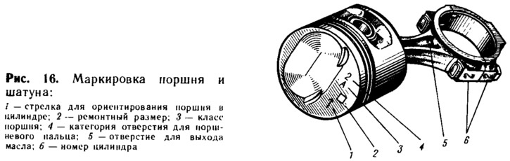
The main dimensions of the piston, connecting rod, piston pin and piston rings of the 2108 engine are given in fig. 15. As well as engine cylinders, pistons are sorted into five classes according to the outer diameter: A, B, C, D and E. The difference in diameters of pistons of neighboring classes is 0.01 mm. Piston class (letter) stamped on its bottom (pic. 16).
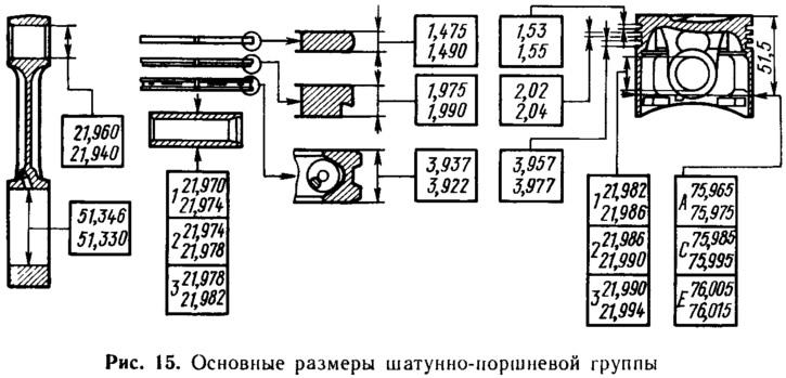
The 2108 and 21081 engines have the same pistons, while the 21083 engine uses pistons and rings with an outer diameter increased by 6 mm. The piston number is cast on the inside of its skirt.
It is possible to measure the piston diameter to determine its class in only one place: in a plane perpendicular to the piston pin, at a distance of 51.5 mm from the bottom. In other places, the piston diameter is not nominal, since the outer surface of the piston has a complex shape. It is oval in cross section (piston head ovality up to 0.1 mm and skirt ovality up to 0.55 mm), and the smaller axis of the oval coincides with the axis of the piston pin. In height, both the skirt and the piston head have a conical shape and, in addition, the diameter of the head is 0.5 mm less than the diameter of the skirt. This shape makes it possible to compensate for the uneven expansion of the piston when heated by reducing its taper and ovality.
The outer surface of the piston skirt is not smooth, but has many annular microgrooves up to 14 microns deep. Such a surface contributes to a better running-in of the piston to the cylinder walls and reduces friction losses, since oil is retained in the micro-grooves. The bottom of the piston is flat, with an oval recess forming part of the combustion chamber, and with small recesses for the valves. In the lower part of the bosses under the piston pin there are holes for the passage of oil to the piston pin. To improve lubrication conditions, two longitudinal grooves 3 mm wide and 0.7 mm deep are made in the upper part of the finger holes, in which oil accumulates. In the area of the bosses, the height of the skirt is reduced to prevent rubbing against the piston of the crankshaft counterweights.
The hole for the piston pin is offset from the axis of symmetry by 1.2 mm to the right side of the engine. Due to this, a moment of forces acts on the piston, pressing it against the cylinder walls always in the same position. Therefore, there is no knocking of the piston against the cylinder walls when it passes through the top dead center. However, this requires the piston to be installed in the cylinder in a strictly defined position. When assembling the engine, the pistons are installed so that arrow 1 (pic. 16) on the bottom of the piston was directed towards the front of the engine.
Piston: the pin is inserted into the piston with a clearance of 0.008... 0.016 mm. In order to achieve such a high-precision clearance in mass production, the pistons are sorted by the diameter of the piston pin hole and the pins by the outer diameter at 0.04 mm into three categories. Number (1,2, 3), indicating the category of the piston, as well as the class, is stamped on its bottom (see fig. 16). During the assembly of the engine, the piston and pin are taken in the same category, which ensures that the required clearance is obtained. The correctness of their pairing is checked by inserting an oiled finger into the piston. The finger should easily enter the piston by pressing the hand and not fall out of it under the influence of its own weight.
The pistons in an engine must be of equal mass to reduce vibrations in the reciprocating parts. During manufacture at the factory, the maximum deviation of the mass of pistons +5 g is strictly maintained. Therefore, when assembling engines 2108, select pistons of the same mass group or adjust their mass) removing excess metal is not required.
Spare parts are supplied with pistons of nominal size of only three classes - A, C and E. This is enough to select a piston for each cylinder during engine repair, since pistons and cylinders are divided into classes with some size overlap. For example, class C pistons can fit class B and D cylinders. The main thing when choosing a piston is to provide the necessary mounting clearance (0.025...0.045 mm) between piston and cylinder.
In addition to pistons of nominal size, repair pistons are also supplied as spare parts, with an outer diameter increased by 0.4 and 0.8 mm. These pistons are intended for installation in overhauled cylinder blocks, in which the cylinders are bored and honed to the next repair size. On the bottoms of the repair pistons are marked in the form of a square 2 (see fig. 16) or a triangle. A triangle corresponds to an increase in the outer diameter of 0.4 mm, and a square corresponds to 0.8 mm.
Piston rings
Piston rings provide the necessary seal between the piston and cylinder walls and remove heat from the piston to its walls. They are pressed against the walls of the cylinder under the action of their own elasticity and gas pressure. Three cast iron rings are installed on the piston - two compression (sealing) and one (bottom) oil scraper, which prevents oil from entering the combustion chamber.
The top compression ring operates in conditions of high temperature, corrosive combustion products and insufficient lubrication. Therefore, to increase wear resistance, its outer surface is chrome-plated, and to improve running-in, it is made convex (barrel-shaped) forms.
The lower compression ring has a recess at the bottom to collect oil during the down stroke, while performing the additional function of an oil drop ring. The surface of the ring is phosphated to increase wear resistance and reduce friction against the cylinder walls.
Oil scraper ring - with chrome-plated working edges and with a groove on the outer surface, into which oil is collected, removed from the cylinder walls. Then it flows through the slots in the ring into the piston groove and from there flows into the oil sump. A coiled steel spring is installed inside the ring, which unclenches the ring from the inside and presses it against the cylinder walls.
Repair rings are made (just like pistons) with an outer diameter increased by 0.4 and 0.8 mm.
Piston pin
Piston pin steel tubular section with a wall thickness of 3.5 mm. To increase hardness and wear resistance, its outer surface is cemented and hardened by high-frequency currents. In the upper head of the connecting rod, the pin is installed with an interference fit of 0.010... 0.042 mm. This press fit prevents it from axial movement in the piston.
According to the outer diameter, the fingers are sorted into three categories through 0.004 mm, respectively, to the categories of pistons. The ends of the fingers are painted in the appropriate color: blue - the first category, green - the second, red - the third.
Connecting rod
Engine connecting rod - forged steel I-section. Its lower head is detachable, and the plane of the separation is perpendicular to the axis of the connecting rod rod. The crankshaft connecting rod bearing shells are installed in this head.
The connecting rod is processed together with the cover. In order not to confuse the covers during assembly, the connecting rod and the corresponding cover are stamped with the number 6 of the cylinder (see fig. 16), in which they are installed. When assembling, the numbers on the connecting rod and cap must be on the same side. The connecting rod cap is attached to the connecting rod with two bolts with self-locking nuts. For precise centering of the bolts, their outer surface and the hole in the connecting rod are machined with high precision, and there is a belt near the bolt head, with which the bolt is pressed into the hole.
Where the bottom head of the connecting rod passes into the rod, there is a hole through which oil is sprayed onto the piston and cylinder walls. When assembling the connecting rod and piston group, the connecting rod must be positioned so that the hole on it and the arrow on the piston are directed in the same direction.
connecting rods (just like pistons) must have the same mass. The mass of the upper head is adjusted with a tolerance of±2 g, and the lower head is±3 g. This is ensured by removing excess metal from the bosses on the upper head of the connecting rod and on the cover of the lower head. Thus, the total mass of the connecting rod is adjusted to a tolerance of±5 g.
For all engines (2108, 21081 and 21083) identical rods are installed. But with connecting rods of old engines (type 2101-2103) they are not interchangeable, as they are 15 mm shorter than them.
Crankshaft
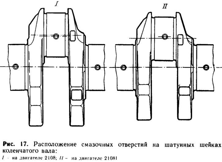
On engines 2108 and 21083, the same crankshafts are installed. On the 21081 engine, due to the smaller piston stroke, another crankshaft is used, with a distance between the axes of the connecting rod and main journals reduced by 5.2 mm. The 21081 crankshaft can be identified by its overall dimensions and the location of the lubrication holes on the crankpins. For crankshafts 21081, these holes are offset by 3.7 mm from the axis in the direction from the main journals, and for crankshafts 2108 - by 1.5 mm in the opposite direction from the axis (pic. 17).
The crankshaft is the main power part of the engine, which perceives the action of gas pressure and inertial forces. It is cast from high-strength special cast iron. To reduce deformations during engine operation, the shaft is made five-bearing and with a large overlap of the main and connecting rod journals. High fatigue strength is provided by smooth transitions between the necks and cheeks and careful processing of stressed areas. High wear resistance of the shaft journals is achieved by a large diameter of the journals (This reduces the specific loads in the bearings) and surface hardening of the necks by high frequency currents to a depth of 2...3 mm.
The crankshaft journals have counterweights cast in one piece with the shaft. They balance the centrifugal forces that occur during engine operation, from the masses of the connecting rod journal, as well as from parts of the connecting rod and piston. Due to this, the main bearings are unloaded from the action of centrifugal forces and engine vibrations are reduced. In addition, the crankshafts are balanced to reduce vibrations. Since this balancing is done without a flywheel, both crankshafts and flywheels are interchangeable.
In the body of the crankshaft are drilled nals connecting the 1st, 2nd, 4th and 5th main journals with the connecting rod. Oil is supplied through these channels to lubricate the connecting rod bearings. Technological outlets of the channels are closed with cap steel plugs, which are pressed in and minted at three points.
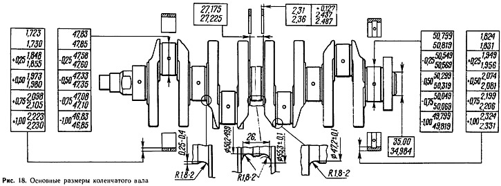
The main dimensions of the crankshaft and bearing shells are given in fig. 18. Main and connecting rod journals are processed with a high degree of frequency and accuracy, since the gap between the necks and liners should be within 0.02... 0.07 mm for connecting rod and 0.026... 0.073 mm for main journals, and the allowable wear gap should not exceed 0.1 and 0.15 mm, respectively.
It is possible to regrind the crankshaft journals during repairs with a diameter reduction of 0.25; 0.5; 0.75 and 1 mm. The journals are ground if they are worn to a diameter that is 0.005 mm less than the minimum diameter for a given crankshaft size, and also if the ovality of the journals is more than 0.03 mm or there are scuffs on them. The diameters of the repair dimensions of the necks are also indicated in Fig. 18.
The front and rear ends of the crankshaft are sealed with self-compressing rubber seals. The front oil seal is pressed into the oil pump cover, and the rear one is installed in a holder that is attached to the cylinder block. Two drive belt pulleys are attached to the front end of the crankshaft. One pulley (jagged) serves to drive the camshaft and is mounted on a segment key. Another pulley transmits rotation to the generator. It is mounted on a pin pressed into a toothed pulley and is centered by a cylindrical belt. Both pulleys are bolted. In addition, the front end of the crankshaft drives the oil pump drive gear, which is fixed on the shaft with two flats.
Inserts
The shells of the main and connecting rod bearings of the crankshaft are thin-walled, bimetallic, with radial holes for the passage of oil. They are made of steel tape coated with a layer of antifriction alloy AMO1-20 (79% aluminium, 20% tin and 1% copper) 0.4... 0.5 mm thick. Between the steel base and the alloy is a thin layer of pure aluminum. The shells of each bearing consist of identical halves. They are kept from turning by the protrusions included in the grooves of the connecting rod or main bearing.
The upper shells of the main bearings have grooves on the inner surface for the passage of oil to the connecting rod bearings. The bottom liners since 1988 are installed without a groove; But until 1988, they also had a groove and were interchangeable with the top liners. Connecting rod bearings differ from main bearings in diameter, thickness and the absence of grooves on the inner surface. Upper and lower connecting rod bearings are interchangeable.
Bearing shells are made as normal thickness, and increased (see fig. 18) under the necks of the cranked hall, reground with a decrease of 0.25; 0.5; 0.75 and 1 mm.
Thrust half rings
Thrust half rings are installed in the sockets of the cylinder block on both sides of the middle (third) main bearing. They perceive axial loads acting on the crankshaft and limit its axial movement. Semi-rings are made as normal thickness, and increased by 0.127 mm (see fig. 18). By selecting the thickness of the half rings, the axial free play of the crankshaft is regulated, which should be within 0.06... 0.26 mm on a new engine and not exceed the maximum: allowable - 0.35 mm when worn.
Front and rear half rings are made of different materials. The semi-ring mounted on the rear side of the 3rd bearing is subjected to increased loads from the clutch side and is therefore made of powder material. This material has a yellowish color and consists of 87...90% copper, 9.5...10.5% tin and 0.5...1% carbon. A semi-ring made by pressing from such a material has porosity. It is impregnated with oil and resists frictional wear well.
The front half rings carry less load and therefore, like the liners, they are made of steel and aluminum, with a thickness of the anti-friction layer on the end surface of 0.3... 0.5 mm. On the side of the anti-friction layer, there are two vertical grooves for the passage of oil. This side of the semicircle (both front and rear) must face the thrust surfaces of the crankshaft.
Flywheel
Flywheel 12 (see fig. 9) serves to ensure the smooth operation of the engine. It stores kinetic energy during working strokes in the cylinders and gives it to the crank mechanism for three other cycles. It also brings the crankshaft out of dead spots. The flywheel is cast iron and has a steel ring gear that is hot pressed onto the flywheel. Crown teeth are hardened with high frequency currents to increase wear resistance and strength.
The flywheel is attached to the crankshaft flange with six self-locking bolts, under which one common washer is placed. It must be installed so that the label (cone-shaped hole) near the rim was against the connecting rod neck of the fourth cylinder. The label is used to determine the top dead center in the first and fourth cylinders. The flywheel is centered by a cylindrical protrusion on the crankshaft.
To create pulses in the TDC sensor, a steel pin is pressed into the flywheel rim, and to adjust the ignition timing, there is a mark 2 on the outer surface of the flywheel (see fig. thirty).