
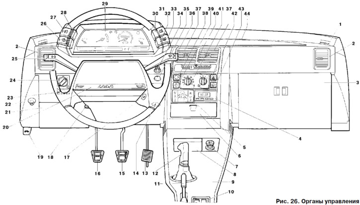
1 - front door glass blowing nozzle.
2 - side nozzles of the ventilation and interior heating system.
3 - glove box cover (see fig. 12).
4 - clock (see fig. 13) or (in a variant) trip computer (see fig. 37).
5 - display unit of the onboard control system (see fig. 36).
6 - radio socket cover. the installation of radio equipment is provided, corresponding in size and method of fastening to international standards (ISO 7736, DIN 75500). Installation of radio equipment should be carried out only on PCCC certified by the manufacturer with a mandatory mark in the service book.
7 - cigarette lighter (works with the ignition on). To use, press the handle of the movable part to a fixed position. After about 20-27 seconds, the moving part automatically returns to its original position, the cigarette lighter is ready for use.
8 - front ashtray.
9 - floor tunnel lining.
10 - control units (see fig. 34). Installed as a variant.
11 - parking brake lever. Moving the lever up activates the rear wheel brake pads. To return the lever to its original position, press the button on the end of the lever handle. In case of emergency, the parking brake can be applied while driving to slow down the vehicle, or it can be used simultaneously with the service brakes.
12 - gear lever. The gearshift pattern is printed on the lever handle.
13 - accelerator pedal.
14 - cartridge for connecting a portable lamp. Installed as a variant.
15 - brake pedal.
16 - clutch pedal.
17 - ignition switch (see fig. 31).
18 - handle for adjusting the angle of the steering column. To set the steering wheel in a comfortable position for steering, lower the handle down and after the desired adjustment, tighten the handle, raising it to its original position.
19 - hood lock drive handle (see fig. 14).
20 - horn switch. In the variant, when the vehicle is equipped with an airbag, the use of a sound signal is carried out by pressing the movable part of the airbag module without applying shock loads.
21 - mounting block cover.
22 - switch for the electric lock of the trunk or tailgate (in a variant). To unlock the lock, press the button.
23 - button for locking the cover of the mounting block.
24 - headlight hydraulic corrector drive handle. A device that allows you to adjust the angle of inclination of the headlight beam by turning the handle, depending on the load of the car, so that drivers of oncoming vehicles are not blinded by low beam headlights.
25 - switch lever for direction indicators and headlights (see fig. 33).
26 - outdoor lighting switch. When the key is pressed to the first fixed position, the side lights are turned on, to the second fixed position, the dipped headlights are additionally turned on with the ignition on. The symbolism on the key is highlighted if the instrument lighting is on.
27 - front fog lamp switch. It is installed on the car instead of the plug, if it is equipped with fog lights. The fog lights are turned on and off by pressing the button while the parking lights are on. The symbolism on the key is highlighted if the instrument lighting is on.
28 - control lamp for turning on the front fog lights. The lamp lights up green when the front fog lamps are turned on.
29 - instrument cluster (see fig. 28).
30 - control lamp for turning on the rear fog light. Lights up in orange when the rear fog light is on.
31 - rear fog light switch. The fog lights in the rear lights are switched on and off by pressing a button. The symbolism on the button is highlighted if the instrument lighting is on. In a variant, the fog lights in the rear lights turn off automatically when the vehicle ignition is turned off. To turn it on again with the headlights on, press the button again.
32 - control lamp for turning on the rear window heating. Lights up in orange when the heated rear window is turned on.
33 - rear window heating switch (see fig. 38).
34 - instrument lighting controller. By turning the knob, the brightness of the instrument lighting and the illumination of symbols is adjusted when the external lighting is on.
35 - immobilizer status indicator. It is installed on cars equipped with an electronic anti-theft system and is designed to read the code from the code keys.
36 - lever switch cleaners and washer glass (see fig. 33).
37 - central nozzles of the interior ventilation and heating system.
38 - recirculation switch (in the variant - together with the air conditioner) (see fig. 38).
39 - air conditioner switch (in a variant) (see fig. 38).
40 - air flow control lever for the heating and ventilation system (see fig. 38).
41 - block of the automatic heating control system (see fig. 38).
42 - alarm switch. When the button is pressed, the flashing light of all direction indicators and the corresponding control lamps in the instrument cluster is switched on. The alarm is turned off by pressing the button again. The symbolism on the button is highlighted if the instrument lighting is on.
43 - switch cleaners and headlight washer (in a variant). The headlight wipers and washer are turned on by pressing the switch button if the headlights are on, and are turned off when the button is released. The symbolism on the button is highlighted if the instrument lighting is on.
44 - windshield blower nozzle.