




The cylinder block is cast iron, with bored cylinders. The internal cavities of the cylinder block for the coolant are formed during its casting, and the oil supply channels are made by drilling. In the lower part of the cylinder block there are five supports of the crankshaft main bearings. The crankshaft main bearing caps are not interchangeable and are marked with the bearing serial number, starting from the crankshaft pulley. In the second main bearing cap there are two threaded holes for the oil intake mounting bolts. Steel-aluminum liners of the main bearings are installed in the supports and caps. On both sides of the support of the third main bearing there are nests for installing thrust half rings that prevent axial movement of the crankshaft. The front half ring is steel-aluminum, the rear one is metal-ceramic, yellow on both sides.
The pistons are made of aluminum alloy with steel inserts cast into them. Four recesses for valve plates are made in the bottom of each piston. Two compression rings and one oil scraper ring are installed on each piston. For correct orientation, the upper compression and oil scraper rings have the inscription "VAZ" or "TOR" on the upper surface. The lower compression ring is of the scraper type with a groove and a sharp edge on the lower surface. A spring expander is installed inside the oil scraper ring.
Piston pins are of the floating type and are fixed in the pistons by two spring retaining rings.
Connecting rods - steel, forged, with removable caps. A steel-bronze bushing is pressed into the upper head of the connecting rod. The connecting rod caps are not interchangeable and are installed on the connecting rod in only one position. The connecting rods and their caps are marked with the cylinder number.
The oil pan is attached to the cylinder block from below.
The engine lubrication system is combined, under pressure and by splashing. The oil pump is a gear type with internal engagement and is driven from the front end of the crankshaft.
The pump takes oil from the oil pan through the oil intake and forces it under pressure into the engine lubrication system channels. To check the oil level in the oil pan on the right side of the cylinder block (when viewed from the crankshaft pulley side) a dipstick is installed. The oil filter is full-flow, with a paper filter element and a check valve that prevents oil from leaking out of the lubrication system channels into the oil pan after the engine has stopped.
Oil nozzles are installed in the main bearing supports. Oil from the nozzles is supplied to the inner surfaces of the pistons to cool them. Some of the oil gets onto the upper heads of the connecting rods and flows through the conical holes made in them onto the piston pins, lubricating them.
The crankshaft body has drilled channels. When the engine is running, oil from the block gets into the crankshaft channels through the holes in the main bearing shells and main journals and then goes to the connecting rod journals, lubricating them. The technological holes in the channels are closed with stamped steel plugs.
[Information copied from the portal: www.VazBook.ru]
The flywheel is bolted to the crankshaft flange. The crankshaft is balanced together with the flywheel. A mark is made on the flywheel to connect the crankshaft to the flywheel in the required position.
On the left side of the block there is a cavity for installing the coolant pump and a lug for installing the oil filter.
An aluminum cylinder head is installed on top of the cylinder block through a special gasket. It contains two camshafts, 16 valves with guide bushings and seats, and 16 hydraulic tappets. The intake and exhaust camshafts are not interchangeable. The camshaft supports are made in the cylinder head, and their covers are combined into a bearing housing installed on the head. From above, the bearing housing is closed by a cylinder head cover with an oil deflector and an oil filler neck.
The camshafts and coolant pump are driven by a toothed belt from the crankshaft. A guide roller is installed to direct the movement of the belt along the pulleys, and the belt is tensioned by a tension roller. The generator is driven by a poly V-belt from the crankshaft pulley.
Features of the VAZ 2112 engine (1.5i)
(in comparison with the VAZ 2111 engine)
The VAZ 2112 engine is a 16-valve, 1.5-liter engine developed on the basis of the VAZ 2111 engine. Cylinder diameter is 82 mm, piston stroke is 71 mm, compression ratio is 10.5; power - 90.7 hp.
The cylinder block of the VAZ 2112 engine is the same as that of the VAZ 2111 engine, the cylinder head is original with two camshafts. It consists of the cylinder head itself, the bearing housing, four spark plug guide pipes and a cover.
To control the tension and condition of the timing belt, a window is made in its front cover, closed with a removable plug.
Attention. A timing belt break causes the piston to hit the valves. Therefore, it is necessary to regularly check the condition of the belt and replace it in a timely manner.
The intake manifold and receiver are made of aluminum alloy and are connected to each other using rubber couplings. The ignition module is installed on the cylinder head cover. The exhaust manifold is cast iron, its connection with the cylinder head is sealed with a two-layer metal gasket.
Features of the VAZ 21124 engine (1.6i)
(in comparison with the VAZ 2112 engine)
The VAZ 21124 engine is a 16-valve, 1.6-liter engine developed on the basis of the VAZ 2112 engine. Cylinder diameter is 82 mm, piston stroke is 75.6 mm; compression ratio - 10.3; power 89 hp.
The VAZ 21124 engine has a cylinder block that is 2.3 mm higher and an original crankshaft. The piston bottoms have deeper grooves, which slightly reduces the compression ratio, but eliminates the possibility of the piston hitting the valves. The cylinder head has been modernized: the spark plug guide pipes are made directly in the cylinder head. The receiver and intake manifold are non-detachable, made of plastic as a single block. The exhaust manifold is steel, combined with a catalytic converter (catalytic converter). Its connection with the head is sealed with a two-layer metal gasket. The ignition module is replaced by four ignition coils installed in spark plug wells. The front timing belt cover is without an inspection window and is divided into two parts.
Note: On the VAZ 2112 (1.5) engine, the cylinder head has removable spark plug guide tubes; exhaust manifold without catalytic converter (catalytic converter); instead of four ignition coils, an ignition module is installed; the inlet module consists of two separate elements - a receiver and a pipeline.
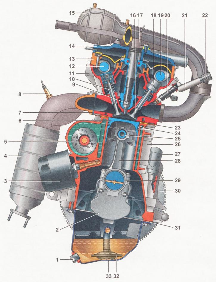
Cross-section of the VAZ 21124 engine (1.6i): 1 - oil pan drain plug; 2 - crankshaft; 3 - oil filter; 4 - catalytic collector; 5 - coolant pump; 6 - piston; 7 - catalytic collector gasket; 8 - oxygen concentration sensor; 9 - spark plug; 10 - exhaust valve; 11 - cylinder head; 12 - exhaust camshaft; 13 - camshaft bearing housing; 14 - cylinder head cover; 15 - intake module; 16 - inlet valve; 17 - ignition coil; 18 - hydraulic pusher; 19 - intake camshaft; 20 - nozzle; 21 - fuel rail; 22 - fuel rail diagnostic connector; 23 - cylinder head gasket; 24 - piston rings; 25 - piston pin; 26 - cylinder block; 27 - crankcase ventilation system nipple; 28 - connecting rod; 29 - connecting rod bearings; 30 - flywheel; 31 - Oil pan gasket; 32 - oil intake; 33 - engine oil pan