




Technical specifications
- Maximum output current at 13 V and rotor speed of 5000 min⁻¹, A — 55
- Adjustable voltage limits, V — 14.1±0.5
- Engine-generator gear ratio: 1:2.04
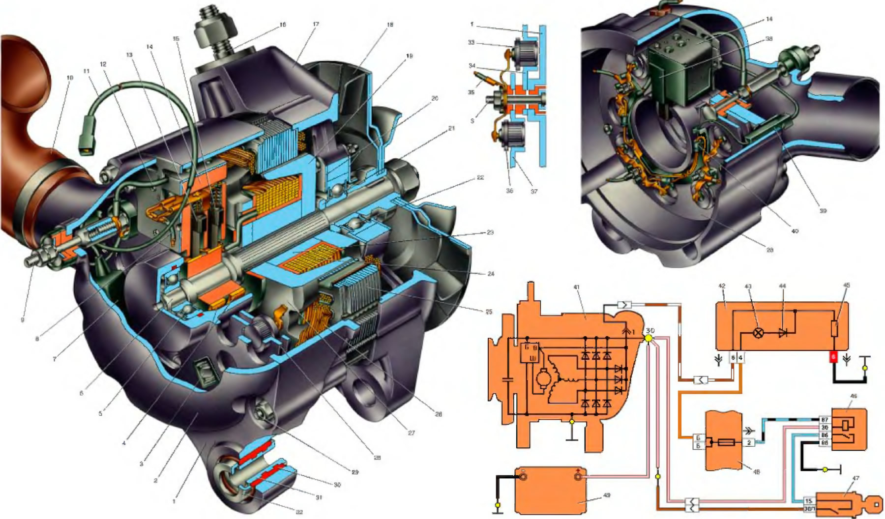
Open large image in new tab »
1. Generator cover from the slip ring side; 2. Protective cover; 3. Bolt for fastening the rectifier block and phase terminals of the stator winding; 4. Slip rings; 5. Anchor shaft ball bearing from the slip ring side; 6. Rotor shaft; 7. Capacitor 2.2uF ±20%; 8. Common output wire of additional diodes; 9. Extension of the terminal bolt (terminal "30" of the generator for connecting consumers); 10. Air intake; 11. Generator terminal "61" wire; 12. Wire of output "B" of voltage regulator; 13. Brush connected to terminal "B" of the voltage regulator; 14. Voltage regulator; 15. Brush connected to the output "W" of the voltage regulator; 16. Stud for fastening the generator to the tensioner; 17. Generator cover, drive side; 18. Fan impeller with generator drive pulley; 19. Rotor pole piece on the drive side; 20. Bearing mounting washers; 21. Distance ring; 22. Ball bearing of rotor shaft on drive side; 23. Steel bushing; 24. Rotor winding (excitation winding); 25. Stator; 26. Stator winding; 27. Rotor pole piece from the slip ring side; 28. Rectifier block; 29. Generator tie bolt; 30. Buffer bushing; 31. Bushing; 32. Pressure sleeve; 33. Negative valve, having a "minus" of rectified current on the body; 34. Negative valve holder; 35. Phase terminal of the stator winding; 36. A positive valve having a rectified current "plus" on its body; 37. Positive valve holder; 38. Brush holder; 39. Output "61" (common terminal of additional diodes); 40. Additional diode (to supply the excitation winding); 41. Generator; 42. Instrument cluster; 43. Battery charge indicator lamp; 44. Diode; 45. Resistor 51 Ohm. 5 W; 46. Ignition relay; 47. Ignition switch; 48. Main fuse box; 49. Battery.
The text is copied from the online portal VazBook