
Warning! Replacing or repairing suspension parts can change wheel alignment, so checking wheel alignment is a must.
For a new run-in vehicle in curb condition with a payload of 3136 N (320 kgf) [4 people and 392 N (40 kgf) cargo in the trunk] the angles of the front wheels should be as follows:
- camber…..0°±30'
- convergence….. (0±1) mm
- pitch angle…..1°30'±30'
Before wheel alignment, check the following:
- air pressure in tires;
- radial and axial runout of wheel disks: axial should not exceed 1 mm, radial - 0.7 mm;
- free play (backlash) steering wheel;
- free play (backlash) in the bearings of the front wheel hubs;
- technical condition of parts and suspension units (absence of deformations, destruction and wear of rubber-metal hinges, unacceptable settlement of the upper support of the suspension strut).
Eliminate the observed faults.
After placing the car on the stand, just before checking the corners, «press» car suspension, applying 2–3 times a force of 392–490 N (40–50 kgf), directed from top to bottom, first at the rear bumper, and then at the front. In this case, the wheels of the car must be parallel to the longitudinal axis of the car.
When checking and adjusting wheel alignment, first check and adjust caster angle, then camber, and lastly toe-in.
The angle of the longitudinal inclination of the axis of rotation. If the angle does not match the data above, change the number of shims installed on both ends of the suspension braces. To increase the angle of the longitudinal inclination of the axis of rotation, reduce the number of washers on the brace in the front or rear of it. Conversely, to reduce the angle, add the number of washers, but only in the back of the guy, since in front this is not always possible due to the short threaded part of the guy. When changing the number of washers on the brace, make sure that the chamfers on the washers face the thrust end of the brace. Follow the same rule when installing the internal thrust washer of the rubber-metal joint when the shims are completely removed. If these requirements are not observed, the tightening of the nuts for fastening the guy wires may loosen.
The number of shims on the extension should not be more than two in front and four in the back.
In order not to change the position of the brace relative to the suspension arm when adjusting the longitudinal inclination of the axis of rotation, use a special device that fixes the brace relative to the lever and thus does not allow the brace to rotate due to forces when tightening the nut securing the brace to the arm. This requirement must be observed in order to prevent premature wear of the rubber-metal hinge and the rubber cushion, on which the ends of the extension rest. When installing or removing one shim, the caster angle of the steering axis changes by approximately 19'.
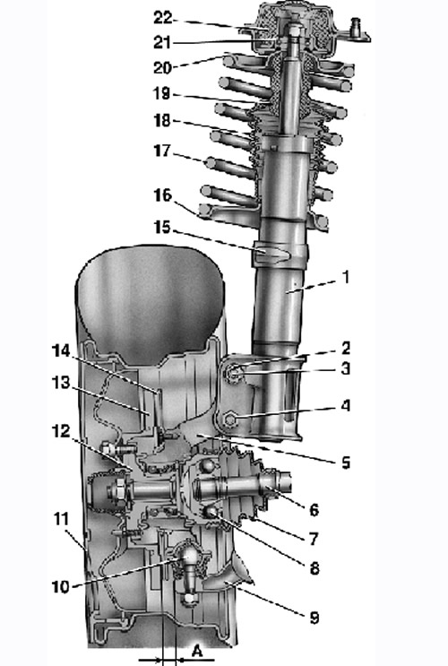
Front suspension assembly: A - control size; 1 - telescopic stand; 2 - nut; 3 - eccentric bolt; 4 - nut; 5 – rotary fist; 6 - front wheel drive shaft; 7 - protective cover of the hinge; 8 - outer hinge of the shaft; 9 - lower lever; 10 - ball bearing; 11 - decorative disc (cap) wheels; 12 - hub; 13 - brake disc; 14 - protective cover; 15 - rotary lever; 16 - lower support cup; 17 - suspension spring; 18 – a protective cover of a telescopic rack; 19 - compression stroke buffer; 20 - upper support cup; 21 - bearing of the upper support; 22 – the top support of a rack
Camber angle of the front wheels. If the camber angle is out of specification, adjust it. To do this, loosen the nuts of the upper and lower bolts and, turning the upper adjusting bolt 3 (see fig.), set the desired camber angle. At the end of the adjustment, tighten the nuts to a torque of 88.2 Nm (9 kgf·m).
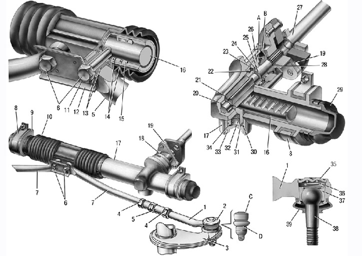
Steering gear assembly with drive: 1 – a tip of steering draft; 2 - ball joint of the tip; 3 - rotary lever; 4 - locknut; 5 - thrust; 6 - bolts for fastening the steering rods to the rack; 7 – internal tips of steering rods; 8 – a bracket of fastening of the steering mechanism; 9 – a support of the steering mechanism; 10 - protective cover; 11 - locking plate; 12 - connecting plate; 13 - rubber-metal hinge; 14 - damping rings; 15 – rack support sleeve; 16 - rail; 17 - steering gear housing; 18 - coupling bolt; 19 – flexible coupling flange; 20 - roller bearing; 21 - drive gear; 22 - ball bearing; 23 - retaining ring; 24 - protective washer; 25 - sealing ring; 26 - bearing nut; 27 – an intermediate steering shaft; 28 - anther; 29 - protective cap; 30 - stop sealing ring; 31 - rail stop; 32 - spring; 33 - stop nut; 34 - stop ring nut; 35 - plug; 36 - spring insert; 37 - ball pin insert; 38 - ball pin; 39 - protective cap; A, B - marks on the anther and crankcase; C, D - surfaces on the ball joint and swing arm.
The convergence of the front wheels. If the toe-in is out of specification, loosen the locknuts 4 by turning the rods 5 (see fig.), set the desired convergence. Then make sure that plane C of the ball joint 2 is parallel to plane D of the bearing surface of the pivot arm 3, and then tighten the locknuts 4 to the torque indicated Here.