
Attention! Checking the wheel alignment is mandatory if you are replacing or repairing suspension parts that may result in a change in wheel alignment.
At the new car (before the first maintenance) wheel alignment angles have the following meanings:
- longitudinal angle of inclination of the axis of rotation — 4°+1°–1°30;
- camber — 0°30+40–30;
- convergence - 1-7 mm.
After the first maintenance (after 2000-3000 km of run) and during the further operation of the car, the value of the wheel alignment angles should be:
- longitudinal angle of inclination of the axis of rotation - 4°± 30' (3°30’±30’) *;
- camber – 0°30'±20' (0°5’±20’) *;
- convergence - 2-4 mm (3-5 mm) *.
The difference in the longitudinal angles of inclination of the axes of rotation of the right and left wheels should not exceed 0°30'.
Before wheel alignment check:
- air pressure in tires;
- axial clearance in the bearings of the front wheel hubs;
- shock absorber serviceability (no stem jamming);
- radial and axial runout of tires;
- clearance in the upper ball joints of the suspension;
- steering wheel free play.
Eliminate the detected malfunctions and make the necessary adjustments.
The control and adjustment of the wheel alignment angles can be carried out both on a loaded vehicle and on an unladen one, however, the control of the angles on a loaded vehicle gives more accurate results. Therefore, in critical cases, it is recommended to carry out control and installation of angles on the car under a static load of 3136 N (320 kgf), which corresponds to approximately the weight of four people and a load of 40 kg in the trunk.
The car is loaded either with special loads suspended from the bottom of the body, or with ballast (280 kg), placed on the seat cushions and in the trunk (40 kg). The front seats must be in the middle position of their longitudinal travel. The load in the trunk is evenly distributed. The lack of fuel is compensated by the cargo located on the right side of the trunk area.
After installing the car on the stand, immediately before the control of the corners, the suspension of the car, applying 2-3 times a force of 392-490 N (40-50 kgf), directed from top to bottom, first at the rear bumper, and then at the front. In this case, the wheels of the car must be parallel to the longitudinal axis of the car.
The sequence of checking and adjusting the wheel alignment angles is as follows:
- angle of longitudinal inclination of the axis of rotation;
- collapse angle;
- convergence.
* In parentheses are the values of the angles without load, without brackets - with load.
Pitch Angle
If, when checking, the angle does not correspond to the data given above, change the number of shims 27 (see fig. Front suspension), installed between the axis of the lower arm and the cross member.
To adjust the caster angle of the steering axis - loosen the nuts securing the lever axle to the cross member and change the number of shims under the bolts to obtain the correct caster angle, referring to the table below.
Changing the camber angle and longitudinal inclination of the axis of rotation when changing the number of washers in packages
Number of pucks added to or removed from the bag | Camber | Longitudinal angle of inclination of the axis of rotation of the wheel | |||
Front bolt | rear bolt | Washer thickness, mm | |||
0,5 | 0,8 | 0,5 | 0,8 | ||
1 | 1 | - (7’–9’) | - (11’–14’) | 0 | 0 |
-1 | -1 | (7’–9’) | (11’–14’) | 0 | 0 |
1 | 0 | 0 | 0 | - (18’–20’) | - (29’–32’) |
-1 | 0 | 0 | 0 | (18’–20’) | (29’–32’) |
0 | 1 | - (7’–9’) | - (11’–14’) | (18’–20’) | (29’–32’) |
0 | -1 | (7’–9’) | (11’–14’) | - (18’–20’) | - (29’–32’) |
-1 | 1 | - (7’–9’) | - (11’–14’) | (36’–40’) | (58’–64’) |
1 | -1 | (7’–9’) | (11’–14’) | - (36’–40’) | - (58’–64’) |
Tighten the nuts with a torque wrench and check the caster angle.
Attention! When adjusting the angles of the front wheels, it is allowed to use U-shaped shims, which must be installed with the slot down.
Front camber angle
If the camber angle is out of specification, adjust it by changing the number of shims 27 (see fig. Front suspension), installed between the axis of the lever and the crossbar, guided by the table.
To increase the camber angle, remove the same number of washers from both bolts, and to decrease, add.
Front wheel alignment
1. If the convergence value differs from the norm, loosen the tie-down collars of the side rods and with the key 67.7813.9504 turn both couplings by the same amount in opposite directions; in this way, the couplings are screwed on or unscrewed and change the length of the side rods.
2. After adjusting, install the tie straps with the slot horizontal (toward the rear of the car) up or down by no more than 60°and tighten them in this position. When the nuts are tightened, the edges of the slots of the clamping collars must not touch.
Checking and adjusting the clearances in the front wheel hub bearings
Front wheel bearing adjustment diagram
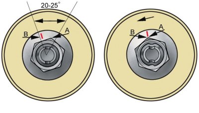
A - the edge of the nut; B - mark on the washer
1. To check the clearance, raise the front of the vehicle, support it on stands and remove the front wheels.
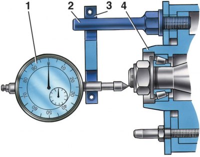
2. Install tool 02.7834.9505 under the wheel bolt. Rest the indicator leg 1 against the end of the re-fist axis, at the zero position of the arrow and, moving the hub 4 along the axis of the steering knuckle, measure the amount of movement (clearance) by indicator (2 - bolt; 3 - bracket).
3. If the gap is greater than 0.15 mm, adjust it in the following order:
- unscrew the adjusting nut from the steering knuckle;
- install a new or used, but on a different vehicle, nut and tighten it to a torque of 19.6 Nm (0.7 kgf·m);
- make a mark on the washer B (see fig. Front wheel bearing adjustment diagram), then loosen the nut by 20–25°so that edge A does not slightly reach mark B;
- lock the nut in this position by pressing the holes in the neck of the nut into the slots at the end of the knuckle shaft.
4. After adjustment, the clearance in the bearing should be within 0.02–0.08 mm.
5. When adjusting the clearance, it should be taken into account that the thread direction on the left knuckle trunnion is right, on the right trunnion - left.
Replacing grease in front wheel bearings
1. Loosen the wheel bolts.
2. Raise the front of the car and support it on stands, unscrew the bolts and remove the wheels.
3. Having unbent petals of locking plates, turn out bolts of fastening of a support of a brake; remove the caliper and take it aside without disconnecting the fluid supply hose so that air and dirt do not get into the hydraulic brake system; the caliper must not hang on the pipelines.
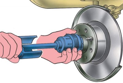
4. Puller 67.7801.9514 remove the front wheel hub cap.
5. Unscrew the adjusting nut, remove the washer.
6. Puller А.40005/1/9В compress the hub, complete with brake disc, outer bearing and oil seal; carefully, so as not to damage the oil seal, remove the hub from the steering knuckle.
7. Rinse the inner cavity of the hub and bearings with kerosene.
8. Before installation, fill the bearing separators with LITOL-24 grease. The space between the outer rings of the bearings, along the inner surface of the hub, evenly fill with the same grease, in the amount of 40 g. Put 25 g of grease into the hub cap before installing it.
9. Being careful not to damage the oil seal, install the hub assembly with the brake disc on the steering knuckle, then the outer bearing inner race, washer and screw in a new or used, but on a different car, nut.
10. Adjust the clearance in the hub bearings as described above.
Wheel balancing
Wheels are balanced on special stands according to the rules described in the instructions attached to the stands. After balancing, the maximum permissible unbalance of the wheel assembly with the tire is 24.5 N·mm (2600 g mm). This unbalance value corresponds to the mass of the weight of about 15 g. The wheel imbalance is eliminated by balancing weights, which are held on the rim by special springs. It is not recommended to exceed the mass of weights in each balancing plane by more than 80 g.