




The circuit for switching on sound signals is shown in Fig. 7-32.
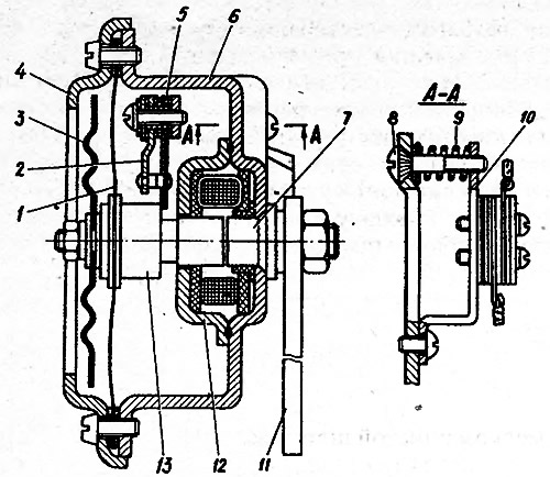
Fig. 7-31. Sound signal: 1 - membrane; 2 - fixed contact holder; 3 - diffuser; 4 - ring; 5 - movable contact plate; 6 - body; 7 - core; 8 - adjusting screw; 9 - adjusting screw spring; 10 - bridge; 11 - signal mounting plate; 12 - yoke; 13 - anchor

Fig. 7-32. Sound signal connection diagram: 1 - sound signals; 2 - sound signal switch. 3 - socket for portable lamp; 4 - fuse box; 5 - generator; 6 - battery
The source is on the website (VAZbook)