

Open large image in new tab »
1. Yoke. 2. Anchor. 3. Winding. 4. Contact block. 5. Core. 6. Cork pads. 7. Adjusting screw. 8. Adjusting screw spring. 9. Bridge. 10. Textolite plate. 11. Fixed contact holder. 12. Body. 13. Moving contact plate. 14. Membrane. 15. Diffuser. 16. Ring. 17. Cargo. 18. Textolite washer. 19. Diffuser housing. 20. Diffuser cover. 21. Steering shaft. 22. Lower contact ring. 23. Steering wheel hub frame. 24. Switch ring cover. 25. Top slip ring. 26. Switch ring hub. 27. Screws for installing the switch ring. 28. Switch ring. 29. The edge of the steering wheel. 30. Screw spring. 31. Spring plate. 32. Limiter. 33. Fixed contact stand. 34. Relay mounting bracket. 35. Foundation. 36. Winding. 37. Anchor. 38. Yarmo. 39. Cover. 40. Horn switch. 41. Sound signals. 42. Battery. 43. Portable lamp socket. 44. Fuse box. 45. Generator. 46. The relay of inclusion of sound signals.
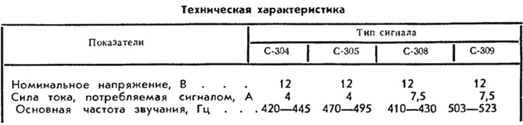
On cars «Zhiguli» two sound signals are installed: one high and the other low tone, and on the VAZ-2101 and VAZ-2102 signals of the type C-304 and C-305, and on the VAZ-2103 - of the type C-308 and C-309. Sound signals are placed in the engine compartment and are mounted on brackets to the front panel of the front end.
The low-pitched C-304 and high-pitched C-305 signals are noise-type electromagnetic signals that produce a sound of a relatively wide frequency range. They differ only in the thickness of the membrane 14: signal C-304 has a thicker membrane than C-305. The signals have a steel case 12, to which a core 5 and a yoke 1 are welded by resistance welding, forming the magnetic system of an electromagnet. Under the yoke there is a winding 3, isolated from the body by cork gaskets 6 and a nylon bushing. Between the body and the ring 16, a membrane 14 made of alloyed hardened steel is clamped. An anchor 2 and a steel diffuser 15 are fixed in the center of the membrane. The diffuser serves to create the sound of the required frequency and timbre. For normal operation of the signal between the armature 2 and the core 5 there must be a gap of 0.4±0.05 mm. This gap is provided by the selection of a gasket between the membrane 14 and the housing 12
Inside the signal housing there is a bridge 9 with a breaker having tungsten contacts. One end of the bridge is attached to the body, and the other can be moved with a screw 7. The holder 11 with a fixed breaker contact and a spring plate 13 with a movable contact, isolated with getinaks gaskets, are fixed on the bridge. A textolite or getinax plate 10 is installed between them. Plate 13 presses the movable contact to the fixed one and therefore the breaker contacts are closed at the off signal.
When the signal is turned on, the current passes through the closed contacts of the breaker and through the winding 3, creating a magnetic force that attracts the armature 2. The armature is attracted, presses the plate 10 with a shoulder of a larger diameter and opens the breaker contacts, turning off the power to the winding. The core 5 is demagnetized and the armature 2 is pulled back by the elastic forces of the membrane. The breaker contacts close and the cycle repeats. With a frequency of 420-495 Hz, the vibrations of the membrane and diffuser create air vibrations and provide sound. The strength and timbre of the sound can be adjusted by moving the edge of the bridge 9 together with the contact plates with the screw 7. This changes the moment of opening and closing the contacts of the breaker.
Signals S-304 and S-305 are designed to be switched on in a two-wire circuit. The winding output 3 and the wire of the plate 13 are soldered to the plugs that are in the plastic block 4 attached to the case. One of the plugs is connected to a current source, and the other is connected through a horn switch to ground.
S-308 signals (low tone) and S-309 (high tone) are called tone-type signals because they produce a sound with a narrow range of frequencies. Their principle of operation is the same as that of the S-304 and S-305 signals, but the design has a number of features. First of all, it is the presence of a diffuser with a cochlear channel that amplifies the sound. The channel dimensions are selected so as to obtain the sound of the required timbre and strength. The C-308 signal has a longer channel length than C-309. The diffuser has a plastic housing 19 and a steel cover 20. The tone of the signal is determined by the weight of the load 17 attached to the anchor. The load is a rectangular steel plate. The S-308 signal has two such plates, while the S-309 signal has only one and smaller ones.
Signals S-308 and S-309 are designed to be switched on in a single-wire circuit, i.e. for them, the second conductor is ground. Therefore, the fixed contact of the interrupter is attached directly to the bridge 9 and, therefore, is connected to the ground. The breaker contacts are opened by a textolite washer 18, which presses the elastic plate 13 with a movable contact. For normal operation of the signal, the gap between the armature and the core must be 1.15±0.05 mm.
Horn switch
The switch is located on the steering wheel and has a different design for VAZ-2101 and VAZ-2103 cars. However, the principle of its operation is the same for both cars and therefore only the switch of the VAZ-2101 and VAZ-2102 cars is described below.
Two contact rings are riveted to the steering wheel hub: the lower 22 and the upper 25, which are electrically connected to each other through rivets. It is pressed against the lower ring 22 by a spring 73 (see sheet 41) pin 49, through which current is supplied from the sound signal. In the upper part of the steering wheel hub, on three screws 27 with springs 30, the hub 26 of the ring 28 of the switch is installed. Ring 28 is cast integrally with hub 26 and is connected to it by two ribs. The hub of the ring can move down on the screws 27, but the springs 30 press it against the heads of the screws, providing a gap between the hub and the upper ring in the range of 0.9-1.5 mm. The screws 27 are wrapped in the steel frame 23 of the steering wheel hub. Therefore, the hub 26 of the ring through the screws 27, the frame 23 and the steering shaft is connected to the ground. When you press on any part of the ring 28, the corresponding edge of the hub 26 is pressed against the upper contact ring 25, closing it with the ground. Sound signals are turned on.
Horn relay
Relay type - RS-528. It is used on VAZ-2103 cars. The relay is mounted in the engine compartment on top of the left wheel mudguard below the headlight relay.
The relay has a getinax base 35, on which a steel yoke 38 with a core and a stand 33 of a fixed contact are fixed. On the core in a plastic frame there is a winding 36. A steel elastic plate 31 with an anchor 37 and a movable contact is riveted to the yoke shelf. A copper plate is placed under it to improve the electrical connection between the yoke and the moving contact. The relay contacts are normally open and close when current passes through the relay coil. The degree of bending of the plate 31 is controlled by the limiter 32 fixed on the core of the relay.