




Car engine electrical equipment VAZ-2121

Battery — technical characteristics
Battery type - 6ST-55P Nominal voltage, V — 12 Nominal capacity at 20-hour discharge mode and electrolyte temperature of 25°C at the beginning of discharge, A h — 55 Discharge...
Battery type - 6ST-55P Nominal voltage, V — 12 Nominal capacity at 20-hour discharge mode and electrolyte temperature of 25°C at the beginning of discharge, A h — 55 Discharge...

Possible battery malfunctions, their causes and methods of elimination
Battery discharge during vehicle operation Electrolyte on the surface of the battery
Battery discharge during vehicle operation Electrolyte on the surface of the battery
Bringing a dry-charged battery into working condition
Cars leaving the factory are equipped with batteries filled with electrolyte and charged. Batteries are supplied as spare parts without electrolyte, dry-charged. To bring such a...
Cars leaving the factory are equipped with batteries filled with electrolyte and charged. Batteries are supplied as spare parts without electrolyte, dry-charged. To bring such a...

Checking the electrolyte level
The electrolyte level should be 5-10 mm higher than the upper edge of the separators or safety shield and not rise above the lower edge of indicator 7 (Fig. 7-3). Fig. 7-3....
The electrolyte level should be 5-10 mm higher than the upper edge of the separators or safety shield and not rise above the lower edge of indicator 7 (Fig. 7-3). Fig. 7-3....

Checking the battery level
To determine the degree of battery discharge, the density of the electrolyte (Table 7-3) is measured using an automotive hydrometer. Table 7-3. Electrolyte density at 25°C, g/cm³...
To determine the degree of battery discharge, the density of the electrolyte (Table 7-3) is measured using an automotive hydrometer. Table 7-3. Electrolyte density at 25°C, g/cm³...
Battery charge
After removing the battery from the vehicle, carefully clean it, especially the top part, and check the electrolyte level. The battery is charged with a current of 5.5 A for...
After removing the battery from the vehicle, carefully clean it, especially the top part, and check the electrolyte level. The battery is charged with a current of 5.5 A for...

Generator — technical characteristics and device
Nominal voltage, V, — 12 Direction of rotation - Right (from the drive side) Maximum output current at 14 V and rotor speed of 5000 min⁻¹, A — 42 Maximum rotor speed, min⁻¹ —...
Nominal voltage, V, — 12 Direction of rotation - Right (from the drive side) Maximum output current at 14 V and rotor speed of 5000 min⁻¹, A — 42 Maximum rotor speed, min⁻¹ —...
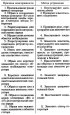
Possible generator malfunctions, their causes and methods of elimination
The indicator light is on or comes on intermittently when the vehicle is moving The indicator lamp does not light when the ignition is turned on The generator is working, the...
The indicator light is on or comes on intermittently when the vehicle is moving The indicator lamp does not light when the ignition is turned on The generator is working, the...
Precautions when repairing a generator
1. The "minus" of the battery must always be connected to the "ground", and the "plus" must be connected to the "30" terminal of the generator. Incorrect reverse connection of the...
1. The "minus" of the battery must always be connected to the "ground", and the "plus" must be connected to the "30" terminal of the generator. Incorrect reverse connection of the...

Generator Checks
Checking the generator on the car If the battery charge indicator light is on when the engine is running, then the generator's serviceability can be roughly determined as follows:...
Checking the generator on the car If the battery charge indicator light is on when the engine is running, then the generator's serviceability can be roughly determined as follows:...

Generator repair
Disassembling the generator After removing the nuts from the extension 21 (Fig. 7-9) of the contact bolt and unscrewing the fastening screws, remove the protective cover 19 with...
Disassembling the generator After removing the nuts from the extension 21 (Fig. 7-9) of the contact bolt and unscrewing the fastening screws, remove the protective cover 19 with...

Voltage Regulator — Design and Warnings
The external appearance of the voltage regulator is shown in Fig. 7-10, and the internal connections diagram is shown in Fig. 7-11. Fig. 7-10. Voltage regulator PP-380: 1 -...
The external appearance of the voltage regulator is shown in Fig. 7-10, and the internal connections diagram is shown in Fig. 7-11. Fig. 7-10. Voltage regulator PP-380: 1 -...

Voltage regulator — testing and adjustment on the stand
Data for verification and adjustment Adjustable voltage at regulator and ambient temperature of 50±3°C, V: at the second stage - 14.2±0.3 at the first stage lower than at the...
Data for verification and adjustment Adjustable voltage at regulator and ambient temperature of 50±3°C, V: at the second stage - 14.2±0.3 at the first stage lower than at the...
Troubleshooting a Voltage Regulator
If the car battery is constantly overcharged, it is necessary, without removing the voltage regulator, to check it under the following conditions: the battery must be fully...
If the car battery is constantly overcharged, it is necessary, without removing the voltage regulator, to check it under the following conditions: the battery must be fully...
Voltage Regulator Repair
The voltage regulator should be repaired only in exceptional cases; it is recommended to replace it. The following operations are allowed for the regulator repair. Replacement of...
The voltage regulator should be repaired only in exceptional cases; it is recommended to replace it. The following operations are allowed for the regulator repair. Replacement of...
Battery charge indicator lamp relay
The PC-702 relay is used to turn on the control lamp on the instrument panel when the generator voltage is insufficient to charge the battery. The relay is installed in the engine...
The PC-702 relay is used to turn on the control lamp on the instrument panel when the generator voltage is insufficient to charge the battery. The relay is installed in the engine...

Starter — technical characteristics and device
Nominal voltage, V — 12 Nominal power, kW — 1.3 Current consumption at maximum power, no more than, A — 260 Current consumption in the braked state, no more than, A — 500 Current...
Nominal voltage, V — 12 Nominal power, kW — 1.3 Current consumption at maximum power, no more than, A — 260 Current consumption in the braked state, no more than, A — 500 Current...

Possible starter malfunctions, their causes and methods of elimination
When the starter is turned on, the anchor does not rotate, the traction relay does not operate When the starter is turned on, the anchor does not rotate or rotates too slowly, the...
When the starter is turned on, the anchor does not rotate, the traction relay does not operate When the starter is turned on, the anchor does not rotate or rotates too slowly, the...

Checking the starter on the stand
To ensure the efficiency of the starter, it is necessary to test its electrical and mechanical data on a bench. The electrical circuit diagram for testing the starter on the stand...
To ensure the efficiency of the starter, it is necessary to test its electrical and mechanical data on a bench. The electrical circuit diagram for testing the starter on the stand...

Starter repair
Malfunctions or damages are eliminated by replacing faulty parts. The only repair operation that can be performed is turning the manifold. Disassembly Loosen the nut on the lower...
Malfunctions or damages are eliminated by replacing faulty parts. The only repair operation that can be performed is turning the manifold. Disassembly Loosen the nut on the lower...

Electrical diagram of the ignition system
The electrical diagram of the ignition system is shown in Fig. 7-18. Fig. 7-18. Ignition system connection diagram: 1 - spark plugs; 2 - ignition distributor; 3 - ignition coil; 4...
The electrical diagram of the ignition system is shown in Fig. 7-18. Fig. 7-18. Ignition system connection diagram: 1 - spark plugs; 2 - ignition distributor; 3 - ignition coil; 4...
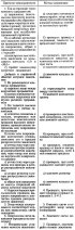
Possible ignition faults, their causes and methods of elimination
The engine does not start Engine runs rough or stalls at idle The engine runs unevenly and unstably at high crankshaft speeds Engine misfires at all speeds The engine does not...
The engine does not start Engine runs rough or stalls at idle The engine runs unevenly and unstably at high crankshaft speeds Engine misfires at all speeds The engine does not...

Setting the ignition timing
To check the ignition timing, there are three marks 1, 2 and 3 (Fig. 7-19) on the timing mechanism drive cover and mark 4 on the crankshaft pulley, corresponding to the TDC of the...
To check the ignition timing, there are three marks 1, 2 and 3 (Fig. 7-19) on the timing mechanism drive cover and mark 4 on the crankshaft pulley, corresponding to the TDC of the...
Checking and adjusting the gap between the contacts of the breaker and in the ignition distributor
The gap between the breaker contacts must be checked in the following order: put the gearshift lever in neutral and apply the parking brake; by rotating the crankshaft, set the...
The gap between the breaker contacts must be checked in the following order: put the gearshift lever in neutral and apply the parking brake; by rotating the crankshaft, set the...
Testing ignition devices on a stand
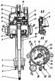
Distributor Attention. Before 1980, the engines used ignition distributors of the P-125 V type (Fig. 7-20). Since 1980, together with the 2107-1107010-20 carburetor, ignition...
Distributor Attention. Before 1980, the engines used ignition distributors of the P-125 V type (Fig. 7-20). Since 1980, together with the 2107-1107010-20 carburetor, ignition...
This section is available on russian, bulgarian, belarusian, ukrainian, serbian, croatian, romanian, polish, slovak, hungarian
More articles from other manuals on VAZ cars:
➠ Electrical equipment: Engine electrics VAZ-2115 (1997-2012)
➠ Electrical equipment: Engine electrics VAZ-2107 (1982-2012)
➠ Power unit: Engine repair VAZ-21011 (1974-1983)
➠ Power unit: Engine repair VAZ-2106 (1976-2006)
➠ Power unit: Engine repair VAZ-2110 (1995-2007)
➠ Electrical equipment: Engine electrics VAZ-2115 (1997-2012)
➠ Electrical equipment: Engine electrics VAZ-2107 (1982-2012)
➠ Power unit: Engine repair VAZ-21011 (1974-1983)
➠ Power unit: Engine repair VAZ-2106 (1976-2006)
➠ Power unit: Engine repair VAZ-2110 (1995-2007)
Share with friends:
- General information
- Vehicle device
- Car VAZ-21219
- Power unit
- Engine repair
- Cooling system
- Lubrication system
- Supply system
- Transmission
- Clutch
- Car gearbox
- Transfer case
- Cardan gear
- Rear axle and gearbox
- Front axle
- Chassis
- Front suspension
- Rear suspension
- Steering
- Brake system
- Body
- Exterior
- Interior
- Doors and windows
- Electrical equipment
- Equipment and devices
- Headlights and lighting
- Engine electrics
- General information
- Vehicle device
- User manual
- Power unit
- Engine repair
- Cooling and lubrication system
- Supply system
- Transmission
- Clutch
- Car gearbox
- Transfer case
- Cardan gear
- Rear axle and shafts
- Front axle and wheel drive
- Chassis
- Wheel suspension
- Steering
- Brake system
- Body
- Exterior
- Interior
- Electrical equipment
- Engine electrics
- Equipment and devices
- General information
- Vehicle information
- Troubleshooting
- Power unit
- Engine repair
- Cooling system
- Fuel system (carburetor)
- Fuel system (injector)
- Ignition system
- Control system
- Exhaust system
- Transmission
- Clutch
- Car gearbox
- Transfer case
- Cardan gear
- Front axle
- Rear axle
- Chassis
- Front suspension
- Rear suspension
- Steering
- Brake system
- Body
- Exterior
- Interior
- Doors, covers and windows
- Ventilation and heating
- Electrical equipment
- Equipment and devices
- Headlights and lighting
- Engine electrics
- Electrical circuits