




Equipment and electrical appliances VAZ-2121

Description of the vehicle's electrical equipment
The electrical equipment is made using a single-wire circuit - the negative terminals of the sources and consumers of electrical energy are connected to the "ground", which acts...
The electrical equipment is made using a single-wire circuit - the negative terminals of the sources and consumers of electrical energy are connected to the "ground", which acts...
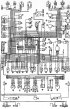
Car electrical system diagram
The electrical circuit diagram of the vehicle is shown in Fig. 7-2. Fig. 7-2. Wiring diagram of the vehicle's electrical equipment units: 1 - side direction indicators - 2 - front...
The electrical circuit diagram of the vehicle is shown in Fig. 7-2. Fig. 7-2. Wiring diagram of the vehicle's electrical equipment units: 1 - side direction indicators - 2 - front...

Sound signals
Two sound signals are installed on the cars (Fig. 7-31): one high-pitched and one low-pitched. The sound signals are located in the engine compartment and are attached to a...
Two sound signals are installed on the cars (Fig. 7-31): one high-pitched and one low-pitched. The sound signals are located in the engine compartment and are attached to a...

Troubleshooting audio signals
The reasons for malfunctions of sound signals may be the following: the switch does not work or is stuck, or the sound signal is damaged. To detect a malfunction, check the...
The reasons for malfunctions of sound signals may be the following: the switch does not work or is stuck, or the sound signal is damaged. To detect a malfunction, check the...

Possible malfunctions of windshield wipers, their causes and methods of elimination
Windscreen wiper motor not working, fuse not blowing Windscreen wiper motor not working, fuse blown Windscreen wiper motor does not operate in intermittent mode Windscreen wiper...
Windscreen wiper motor not working, fuse not blowing Windscreen wiper motor not working, fuse blown Windscreen wiper motor does not operate in intermittent mode Windscreen wiper...

Windscreen wiper repair
The electrical circuit for switching on the windshield wiper is shown in Fig. 7-33. Some windshield wipers may have a thermal bimetallic fuse installed to protect the electric...
The electrical circuit for switching on the windshield wiper is shown in Fig. 7-33. Some windshield wipers may have a thermal bimetallic fuse installed to protect the electric...
Removal and installation the windshield wiper
The windshield wiper is removed from the engine compartment in the following order: remove the brushes with levers; disconnect the wires from the battery and from the windshield...
The windshield wiper is removed from the engine compartment in the following order: remove the brushes with levers; disconnect the wires from the battery and from the windshield...

Disassembly, assembly and technical inspection of the windshield wiper motor
Data for checking the electric motor: Maximum effective torque on the gearbox shaft*, N·m (kgf·m) — 2 (0.2) Current consumption* at a torque of 1 Nm (0.1 kgf·m), no more than, A —...
Data for checking the electric motor: Maximum effective torque on the gearbox shaft*, N·m (kgf·m) — 2 (0.2) Current consumption* at a torque of 1 Nm (0.1 kgf·m), no more than, A —...
Windscreen wiper relay test data
The number of switches per minute at a voltage of 10-14 V and a temperature of -20 to +50°C is 9-17 Electromagnet winding resistance, Ohm — 66±2 Breaker winding resistance, Ohm —...
The number of switches per minute at a voltage of 10-14 V and a temperature of -20 to +50°C is 9-17 Electromagnet winding resistance, Ohm — 66±2 Breaker winding resistance, Ohm —...

Headlight cleaner
The headlight washer connection diagram is shown in Fig. 7-35. Fig. 7-35. Wiring diagram of the headlight cleaner and washer: 1 - Right headlight washer motor; 2 - headlight wiper...
The headlight washer connection diagram is shown in Fig. 7-35. Fig. 7-35. Wiring diagram of the headlight cleaner and washer: 1 - Right headlight washer motor; 2 - headlight wiper...

Possible malfunctions of the heater electric motor, their causes and methods of elimination
The electric motor does not work The motor anchor rotates slowly
The electric motor does not work The motor anchor rotates slowly

Repair of heater electric motor
Data for verification Nominal voltage, V — 12 Nominal power, W — 20 Rotational speed of the anchor shaft with impeller at rated power, min⁻¹ — 3000±150 Current consumption at...
Data for verification Nominal voltage, V — 12 Nominal power, W — 20 Rotational speed of the anchor shaft with impeller at rated power, min⁻¹ — 3000±150 Current consumption at...

Possible malfunctions of control devices, their causes and methods of elimination
The instrument fuse keeps blowing The coolant temperature gauge needle is constantly at the beginning of the scale The coolant temperature gauge needle is constantly in the red...
The instrument fuse keeps blowing The coolant temperature gauge needle is constantly at the beginning of the scale The coolant temperature gauge needle is constantly in the red...

Removal the instrument panel
To remove the instrument panel to replace a faulty device or a burnt-out bulb, press the clamps 3 (Fig. 7-38) with the stitching 4 through the special holes in the lower part of...
To remove the instrument panel to replace a faulty device or a burnt-out bulb, press the clamps 3 (Fig. 7-38) with the stitching 4 through the special holes in the lower part of...

Methodology for troubleshooting devices
The wiring diagram for the instruments is shown in Fig. 7-39. The wiring diagram for the battery charge indicator lamps, side lights, high beam headlights and turn signals is...
The wiring diagram for the instruments is shown in Fig. 7-39. The wiring diagram for the battery charge indicator lamps, side lights, high beam headlights and turn signals is...
Checking the devices
Coolant temperature gauge Device type - UK-193; The device operates together with the TM-106 sensor. With a sensor resistance of 640-1320 Ohm, the arrow should be at the beginning...
Coolant temperature gauge Device type - UK-193; The device operates together with the TM-106 sensor. With a sensor resistance of 640-1320 Ohm, the arrow should be at the beginning...
Checking the sensors of control devices
Fuel level indicator sensor Sensor type BM-168. It is installed in the fuel tank and is attached to it with screws. The sensor has a variable resistor made of nichrome wire. The...
Fuel level indicator sensor Sensor type BM-168. It is installed in the fuel tank and is attached to it with screws. The sensor has a variable resistor made of nichrome wire. The...
This section is available on russian, bulgarian, belarusian, ukrainian, serbian, croatian, romanian, polish, slovak, hungarian
More articles from other manuals on VAZ cars:
➠ Electrical equipment: Equipment and devices VAZ-2110 (1995-2007)
➠ Electrical equipment: Equipment and devices VAZ-2109 (1984-1997)
➠ Electrical equipment: Equipment and devices VAZ-2107 (1982-2012)
➠ Electrical equipment: Equipment and devices VAZ-1111 (1988-1996)
➠ Electrical equipment: Equipment and devices VAZ-21051 (1979-2010)
➠ Electrical equipment: Equipment and devices VAZ-2110 (1995-2007)
➠ Electrical equipment: Equipment and devices VAZ-2109 (1984-1997)
➠ Electrical equipment: Equipment and devices VAZ-2107 (1982-2012)
➠ Electrical equipment: Equipment and devices VAZ-1111 (1988-1996)
➠ Electrical equipment: Equipment and devices VAZ-21051 (1979-2010)
Share with friends:
- General information
- Vehicle device
- Car VAZ-21219
- Power unit
- Engine repair
- Cooling system
- Lubrication system
- Supply system
- Transmission
- Clutch
- Car gearbox
- Transfer case
- Cardan gear
- Rear axle and gearbox
- Front axle
- Chassis
- Front suspension
- Rear suspension
- Steering
- Brake system
- Body
- Exterior
- Interior
- Doors and windows
- Electrical equipment
- Equipment and devices
- Headlights and lighting
- Engine electrics
- General information
- Vehicle device
- User manual
- Power unit
- Engine repair
- Cooling and lubrication system
- Supply system
- Transmission
- Clutch
- Car gearbox
- Transfer case
- Cardan gear
- Rear axle and shafts
- Front axle and wheel drive
- Chassis
- Wheel suspension
- Steering
- Brake system
- Body
- Exterior
- Interior
- Electrical equipment
- Engine electrics
- Equipment and devices
- General information
- Vehicle information
- Troubleshooting
- Power unit
- Engine repair
- Cooling system
- Fuel system (carburetor)
- Fuel system (injector)
- Ignition system
- Control system
- Exhaust system
- Transmission
- Clutch
- Car gearbox
- Transfer case
- Cardan gear
- Front axle
- Rear axle
- Chassis
- Front suspension
- Rear suspension
- Steering
- Brake system
- Body
- Exterior
- Interior
- Doors, covers and windows
- Ventilation and heating
- Electrical equipment
- Equipment and devices
- Headlights and lighting
- Engine electrics
- Electrical circuits