




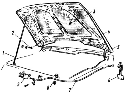
Figure 173. Hood: 1 — hood stop; 2 - hood mounting bolts; 3 — buffer; 4 — hood; 5 - hood hinge; 6 — hood lock drive handle; 7 — drive rod; in — hood support holder; 9 — hood lock.
The hood 4 is hung on hinges 5 along the rear edge, and in the closed position rests on adjustable rubber buffers. The adjustment of the hood position in the body opening is achieved by means of enlarged openings in the hood for bolts 2 for fastening to hinges 5, enlarged openings in the hood lock housing 9 and by changing the position of buffers 3 in height. Bending of hinges 5 is allowed to match the front surfaces of the hood and fenders.
Hood lock (figure 174) is secured with two nuts to the welded bolts on the front crossmember. At the top in the middle part of the body 6 (see figure 174) has a special cutout for fixing the lock pin welded to the hood and holding it from lateral displacement. On the housing, on the axles, the rotor 5 of the lock and the lever 2 are mounted, which are pulled together by one spring. The handle of the lock drive is mounted on the bracket under the instrument panel. To prevent the hood from opening accidentally, a hook 3 of the hood lock is mounted on the housing 6 of the lock, which has a handle in front. The hook holds the hood when the lock is open. When opening the hood, act on the handle, thereby moving the hook to the side and releasing the hood.
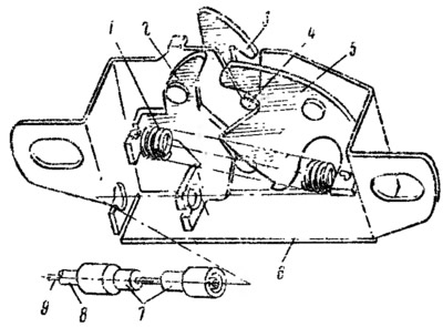
Figure 174. Hood lock (view from the inside): 1 - lever and rotor spring; 2 - lock lever; 3 - hood lock hook; 4 — hood lock retainer; 5 — lock rotor; 6 — lock body; 7 - traction leash; 8 — thrust shell; 9 — lock drive rod.
The bonnet lock is adjusted by shifting the lock using the enlarged oval holes in the lock body.
The article is taken from an online resource VazBook.ru