
On a new, run-in vehicle in curb condition and with a payload of 2205 N, which is distributed at 735 N in the two front seats and 735 N in the center of the rear seat, the wheel alignment must be as follows:
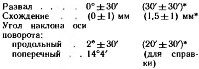
* For equipped vehicle.
Before adjusting the wheel alignment angles, check the air pressure in the tires, the radial and axial runout of the wheel disks (no more than: axial - 1 mm, radial - 0.7 mm), free running (backlash) steering wheel (no more than 5°), free running (backlash) in front wheel bearings (unacceptable), as well as the technical condition of parts and suspension assemblies (absence of deformations, destruction and wear of rubber-metal hinges, wear of the upper support of the suspension strut). Faults found are corrected.
After placing the car on the stand just before the corner control «live through» suspension of the car, applying 2-3 times a force of 392-490 N, directed from top to bottom, first on the rear bumper, and then on the front. In this case, the wheels of the car must be parallel to the longitudinal axis of the car.
The sequence of checking and adjusting the angles of the wheels is as follows: the angle of the longitudinal inclination of the axis of rotation; collapse; convergence.
Angle of longitudinal inclination of the axis of rotation
If this angle does not correspond to the data given above, adjust it with nuts 4 (see fig. 99) with a loosened nut securing the brace to the lower suspension arm. To reduce the angle of the longitudinal inclination of the axis of rotation, nuts 4 are screwed onto the brace, and vice versa, to increase the angle, the nuts are rolled from the brace until the required angle is established.
Front camber angle
If the camber angle differs from the norm, then adjust it. To do this, loosen the nuts of the upper and lower bolts and, turning the upper adjusting bolt 8 (see fig. 97), set the desired camber angle. At the end of the adjustment, tighten the nuts to a torque of 121 Nm.
Convergence
If the convergence does not correspond to the norm, loosen the lock nuts 2 (see fig. 113) and, by rotating the inner tips 3 at the same angle, set the required convergence. In this case, the front wheels should be in the position of the rectilinear movement of the car, and the steering gear rack should be in the middle position, that is, mark A on the steering gear housing and mark B on the anther should be aligned. After adjusting the toe and tightening the locknuts of the inner tips, it is necessary to exclude possible twisting of the steering gear covers.