
The design of the suspension creates a negative rolling shoulder, i.e. the point of intersection of the axis of rotation of the wheel with the roadbed lies on the outside relative to the center of the tire contact patch with the road.
In combination with a diagonal hydraulic brake separation scheme, this makes the car more stable when braking on slippery roads.
The main element of the suspension is a telescopic hydraulic shock absorber strut 7 (pic. 97), the lower part of which is connected to the rotary cam 16 with two bolts 8. The upper bolt passing through the oval hole of the rack bracket has an eccentric belt. Turning the top bolt changes the camber of the front wheels. On the telescopic rack are installed: a coiled coil spring 5, a polyurethane foam buffer 3 of the compression stroke, a sleeve bearing 2 of the slide, and also an upper support 1 of the rack.
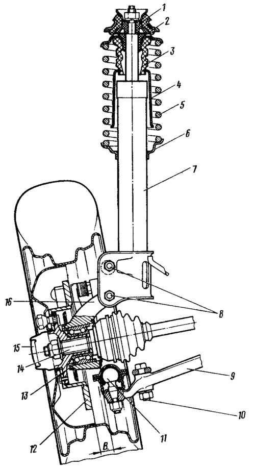
Pic. 97. Telescopic front suspension strut assembly with steering knuckle and wheel hub: 1 - upper support of the suspension strut; 2 - bearing sleeve; 3 - compression stroke buffer; 4 - protective cover; 5 - suspension spring; 6 - lower support cup of the spring; 7 - telescopic rack; 8 — bolts of fastening of a rack to a rotary fist; 9 - lower suspension arm; 10 a bolt of fastening of an extension to the suspension arm; 11 - ball joint; 12 - brake disc; 13 - hub bearing; 14 - splined tip of the outer hinge housing; 15 - hub cap; 16 - knuckle; B - clearance measurement zone in the ball joint of the suspension.
The upper support is fastened with two self-locking nuts 5 (see fig. 126) to the mudguard strut. Due to its elasticity, the support provides «rocking» struts during suspension travel and dampens high-frequency vibrations. The plain bearing allows the column to turn along with the steered wheels.
Details of a telescopic hydraulic shock absorber, shown in fig. 98.
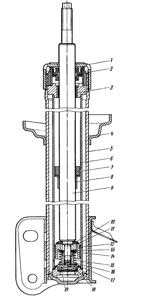
Pic. 98. Telescopic stand: 1 - housing nut; 2 - stuffing box; 3 - rod guide sleeve; 4 - lower support cup of the suspension spring; 5 rack body: 6 - cylinder; 7 - recoil buffer; 8 - recoil buffer stop; 9 - stock; 10 - bypass valve spring; 11 - bypass valve plate; 12 - piston; 13 - recoil valve discs; 14 - recoil valve plate; 15 - recoil valve spring; 16 - nut; 17 - clip of the compression valve; 18 - compression valve plate; 19 - compression valve discs.
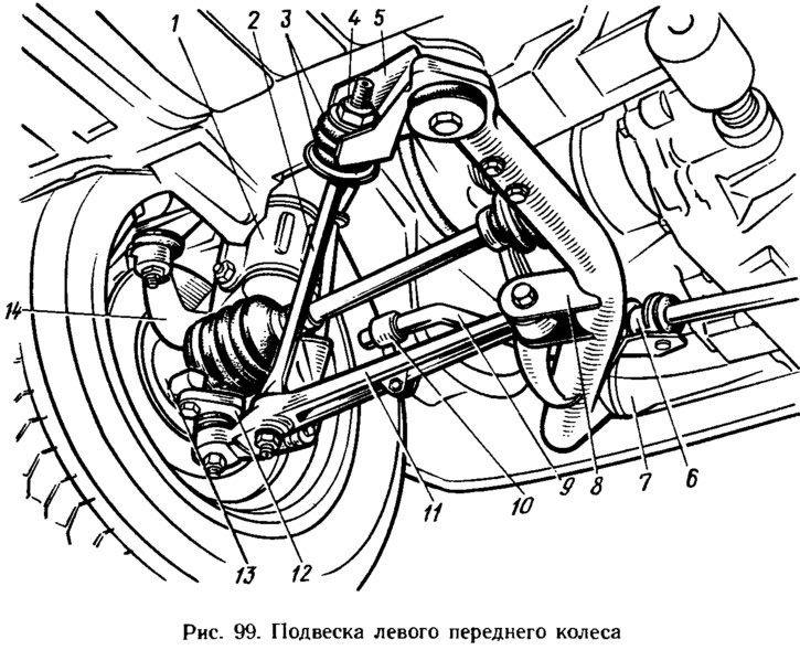
Lower part of the rotary cam 16 (see fig. 97) is connected by a ball joint 11 to the transverse arm 9 of the suspension, the other end of which is connected to the bracket 8 through a rubber-metal hinge (pic. 99) subframe 7. Braking and traction forces are perceived by longitudinal extensions 2, which are bolted to the transverse levers 11, and through rubber cushions 3 - to the brackets 5 of the subframe. Nuts 4 fastening the stretch marks to the subframe regulate the longitudinal inclination of the axis of rotation. On the braces, at the points of their connection with the suspension arms, marks are made for the correct connection of the braces with the suspension arms.
An angular contact bearing 13 is mounted in the steering knuckle (see fig. 97) closed type, on the inner rings of which the wheel hub is installed with an interference fit. The inner race of the bearing is tightened with a nut on the tip 14 of the housing of the outer hinge of the wheel drive.
The axial clearance in the hub bearing is not adjustable.
To ensure tension in the spline connection of the hinge body and the hub, the splines on the shank of the hinge body are made spiral. The threaded part on the shank is lengthened to allow the nut to be screwed on when the hub is not fully seated on the splines.
The anti-roll bar is a 9 bar (see fig. 99), the knees of which are connected through the racks 10 with rubber bushings to the wishbones 11 of the suspension. Medium (torsion) part of the rod is attached to the subframe with 7 brackets 6 through rubber cushions.