
When the hub is pressed out, the bearing can be disassembled and the outer half of the inner ring can remain on the hub. In this case, it is removed with a universal puller. There are two special recesses in the hub for this. Then remove the retaining rings 4 (pic. 101) and mandrel 67.7853.9574 press out the bearing from the steering knuckle.
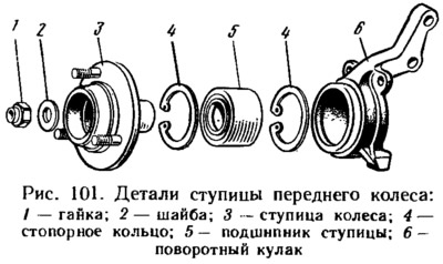
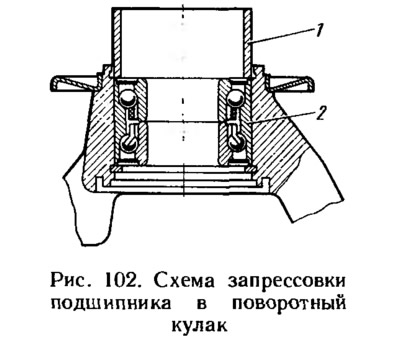
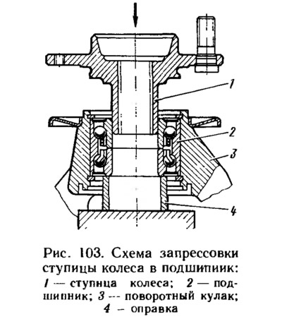
A new bearing is installed in the following order: install the outer circlip 4 (see fig. 101) into the steering knuckle 6 and press the bearing 5. At the same time, make sure that the mandrel 1 (pic. 102) pressed only on the outer ring 2, otherwise it may be damaged. Then, an internal retaining ring is installed and the hub is pressed in with a technological mandrel. When it is pressed in, mandrel 4 (pic. 103) must be supported by the inner ring of the bearing.
After installing the steering knuckle assembly with the hub, a new or used nut is installed on the car, but on a different car, and tightened to a torque of 196.0-235 N·m. Then lock the nut.
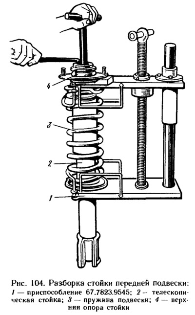
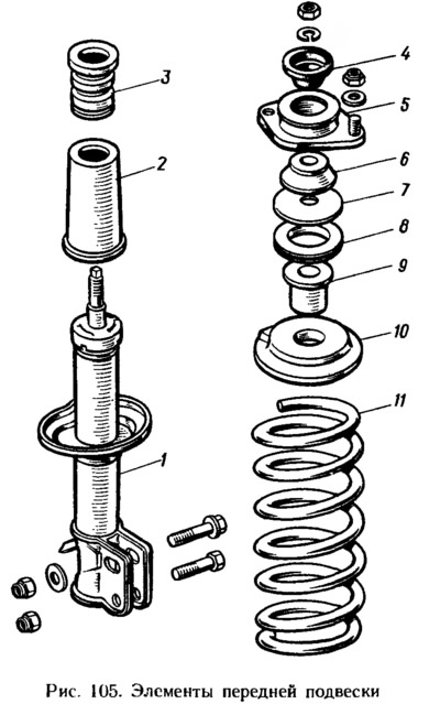
By installing the suspension strut in tool 67.7823.9545 (pic. 104), compress the suspension spring. Holding the stem with the key A.57070, unscrew the nut on the stem. Remove top support 5 (pic. 105) assembled with clips 4 and 6, support washer 7, ring 8 and bushing 9. Having unloaded the spring 11, remove it and the upper support cup 10, and then the buffer 3 of the compression stroke with the casing 2. Before further disassembly of the rack 1, check its condition. With vertical stand (stem up) perform several full stretch-compression strokes, after which the rod should move without dips and jams. The rebound force must be greater than the compression force. In this case, there should be no knocks and other extraneous noises. Liquid leakage, deformation and destruction of the rack body, support cup, brackets are also not allowed. Slight sweating at the top of the strut housing is not a malfunction and is not a reason to replace or repair the suspension strut.
A more accurate assessment of rack performance is carried out on a dyno using a removed diagram, as indicated in the previous section.
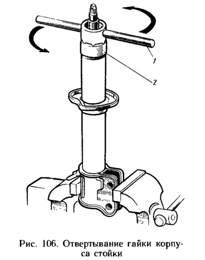
If it is necessary to repair the rack, clamp its bracket in a vice so that the cheeks of the bracket are perpendicular to the jaws of the vice (pic. 106). With this fastening, the possibility of deformation of the rack is excluded. Dismantle the rack using tool kit 67.7824.9518, in the following order:
- unscrew with key 1 (67.7811.9512) (see fig. 106) nut 2 of the body, remove the stem 9 from the body of the rack (see fig. 98) complete with stuffing box 2, guide bushing 3 of the rod, compression stroke limiter and parts of the recoil valve and bypass valve;
- the cylinder 6, complete with the compression valve, is removed from the rack housing and the liquid is drained from the cylinder;
- having installed the compression valve in the mandrel from the kit 67.7824.9518, clamp it in a vice and slightly shake the cylinder by hand until the compression valve is separated from the cylinder;
- clamp the rod in a vice by the flats on its shank and unscrew the nut 16 (see fig. 98) recoil valve, then remove the recoil valve parts 13, 14, 15, piston 12 and bypass valve parts 10, 11 from the stem; freeing the rack housing from the vice, drain the liquid from it;
- the compression valve is disassembled, for which the clip 17 is removed, and then the spring, the plate 18 and the disks 19 of the compression valve are sequentially removed from the housing.
The assembly of the front suspension strut is carried out in the reverse order of disassembly, taking into account the following:
- ensure the cleanliness of the workplace and all parts of the rack;
- make sure that there are no foreign impurities in the liquid, filter it if necessary, make sure that the thread of the recoil valve nut is not damaged when it is unscrewed with a cored stem;
- inspect the stem at the point of punching; if the thread deformation is large and does not allow screwing the recoil valve nut without damaging its thread, then the stem thread is calibrated with a die;
- the throttle disc of the front suspension recoil valve has six grooves along the outer diameter, and the throttle disc of the rear shock absorber has four;
- the throttle disc of the front suspension strut compression valve has three grooves along the inner diameter, and the throttle disc of the rear shock absorber has two;
- the recoil valve nut is tightened to a torque of 12.7–17.5 N·m, after which it is countered by punching the threaded end of the stem in previously undeformed places;
- after assembling the recoil valve, check the free play of the bypass valve plate;
- it is recommended to replace the stem seal with a new one;
- seal working surface (between sealing lips) fill with SHRUS-4 lubricant in the amount of 0.3-0.4 g;
- pour into the rack body and into the cylinder (270±5) cm3 liquid MGP-10, in the rear shock absorber - (143±±) cm3 the same liquid
- after assembling the compression valve, make sure that the valve discs and disks have free play;
- the compression valve is pressed into the cylinder with a tubular mandrel with an inner diameter of 33 mm, after which they are once again convinced that the plate and disks have free play;
- a tubular mandrel with an inner diameter of 35 mm is used to install and press in the rod guide sleeve;
- the nut of the strut housing is tightened with the rod fully extended with the key 67.7811.9512, the tightening torque is 117-147 Nm, at the rear shock absorber the tightening torque is 69-88 Nm;
- springs of the same class are installed on the suspension.
Springs along the length under control load are divided into two classes: A and B. Class A springs are marked with yellow paint on the outer side of the coils, and class B - green. In exceptional cases, if class A springs are installed on the front suspension, and there are no springs of this class for the rear suspension, it is allowed to install class B springs on the rear suspension. But if class B springs are installed on the front suspension, then only class B springs are installed on the rear suspension.
Notes
1. See sec. «Gearbox Assembly».
2. A cylindrical mandrel with a diameter of 25 mm with a support belt with a diameter of 60 mm and a width of 6 mm has a shank with a length of 14 mm and a diameter of 25 mm.