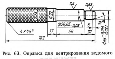
First remove the gearbox (see section 2.2), after which, having unscrewed the bolts, remove the clutch assembly. In this case, it is forbidden to lift it by the thrust flange of the pressure spring. Install the clutch in the reverse order, having first checked the condition of the bearing at the end of the crankshaft. If necessary, replace it using the puller shown in fig. 49. Check the condition of the splines on the driven disk hub and on the gearbox drive shaft and lubricate the splines with a thin layer of LSC-15 or Litol-24 grease. The driven clutch disk is positioned with the protruding part of the hub toward the gearbox and is centered with the A.70081 mandrel (Fig. 63), simulating the splined end of the gearbox drive shaft. Therefore, the gearbox drive shaft can be used instead of the mandrel.