




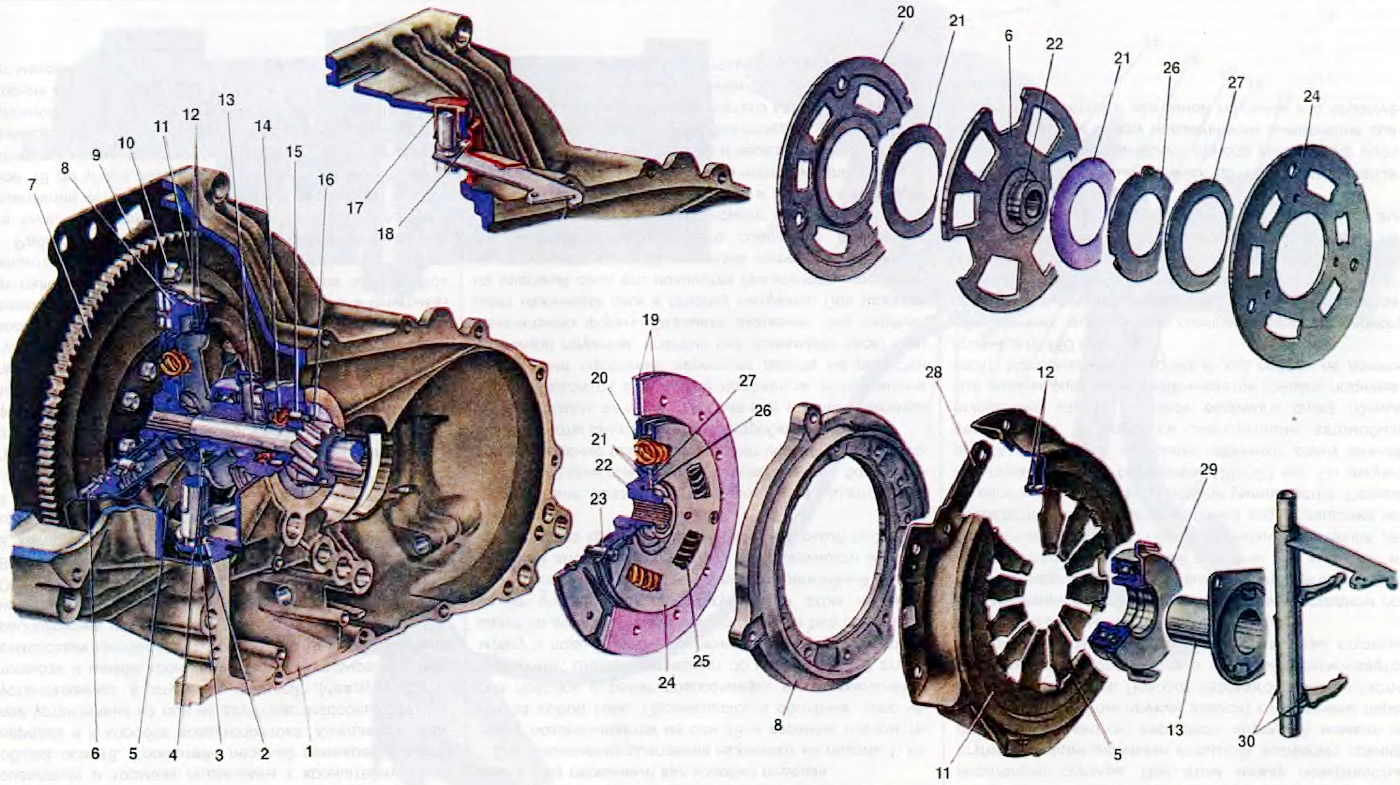
Open large image in new tab »
Figure 16. Clutch: 1. Clutch housing; 2 Clutch release fork shaft support sleeve; 3. Clutch release fork; 4 Clutch release bearing; 5. Pressure spring; 6. Slave disk; 7. Flywheel; 8. Pressure plate; 9. Scale for checking ignition timing; 10. Bolt securing the clutch to the flywheel; 11. Clutch housing; 12. Support rings of the pressure spring; 13. Clutch release bearing sleeve guide sleeve; 14. Primary shaft seal of the gearbox; 15. Primary shaft bearing; 16. Primary shaft; 17. Clutch release fork shaft sleeve; 18. Clutch release fork protective cover; 19. Friction linings of the driven disk; 20. Front damper plate; 21. Damper friction rings; 22. Driven disk hub; 23. Damper stop; 24. Rear damper plate; 25. Damper spring; 26. Spring washer support ring; 27. Damper spring washer; 28. Plate connecting the clutch housing to the pressure plate; 29. Clutch release bearing sleeve; 30. Connecting spring of the clutch release bearing fork and sleeve.
The clutch is secured to the flywheel 7 with six bolts and three dowel pins, which center the clutch relative to the flywheel. It is covered with an aluminum housing 1, which is secured to the engine block. On the engine side, the clutch housing is covered with upper and lower covers. The upper cover has a scale 9 with divisions, and on the flywheel a mark, by which the ignition timing is set and checked. For this purpose, an inspection hatch is made on the housing. A bushing 2 is pressed into the hole in the lower lug of the clutch housing, on which the lower end of the clutch release fork 3 rests. The upper end of the fork enters a plastic bushing 17. The fork lever comes out through the hatch and is connected to the clutch release drive cable. At the exit, the fork lever is sealed with a protective cover 18.
The clutch housing contains seats for the bearings of the primary and secondary shafts of the gearbox. The bearing 15 of the primary shaft is sealed with a seal 14. The guide sleeve 14 of the coupling 29 of the clutch release bearing is bolted to the inner end of the seat of this bearing.
The leading part of the clutch, consisting of the casing 11, the pressure plate 8 and the pressure spring 5, is made as a non-detachable unit and has a rigid connection with the flywheel. This part of the clutch is designed to transmit torque to the driven part of the clutch. The casing 11 of the clutch is stamped from special steel. Three pairs of elastic plates 28 are riveted to it, connecting the clutch casing with the pressure plate 8. Such an elastic connection ensures the transmission of torque from the clutch casing to the pressure plate and the axial movement of the pressure plate in the casing when the clutch is disengaged. In addition, due to the elasticity of the connecting plates, the pressure plate is moved away from the driven disk when the clutch is disengaged. Support rings 12 of circular cross-section are welded into the casing sockets. They are supports for the pressure spring 5, relative to which it deflects when the clutch is disengaged.
The pressure plate 8 is cast iron and has three bosses, through the holes of which the rivets for fastening the elastic plates 28 pass. On the side of the clutch housing, the pressure plate has recesses for ventilation of the clutch and an annular protrusion on which the outer edge of the pressure spring presses.
The pressure spring 5 is stamped from sheet steel and has the shape of a truncated cone. Radial slots dividing the spring into twelve sectors form petals on the surface of the spring that function as clutch release levers. The slots on the periphery pass into shaped holes into which the projections of the clutch housing enter during assembly, after which their ends are bent by 100-110°. In this case, the spring is placed between the support rings 12. The ends of the petals at the point of contact with the clutch release bearing are bent to a rounded point. The pressure spring is phosphated and subjected to shot blasting.
The driven part of the clutch consists of a driven disk 6 assembled with friction linings 19 and a torsional vibration damper (damper). The driven part is located on the splines of the primary shaft of the gearbox and, receiving torque from the parts of the driving part, transmits it to shaft 16.
The driven disk is steel with shaped slots dividing it into eight petals bent in different directions. This gives a wave-like shape to the working surface of the disk. Friction linings 19 are riveted to the petals of the driven disk independently of each other with steel rivets. The heads of the rivets are recessed into the holes of the linings, and their rods are riveted from the side of the disk through the holes of the opposite lining. Thus, both linings are riveted to each petal, each with its own rivet. Such fastening of the linings preserves the wave-like surface of the driven disk, and this ensures smooth engagement of the clutch, since the driven disk gradually becomes flat, as the force pressing it against the surface of the flywheel increases. In this case, the driven disk initially slips relative to the surfaces of the flywheel and pressure plate, and the transmitted torque increases gradually. This protects the transmission parts from overloads and ensures smooth starting. For the same purpose, as well as for damping torsional vibrations, the driven disk is connected to the hub 22 through the parts of the torsional vibration damper, which provide an elastic connection between them. In the hub flange, six rectangular windows and three horseshoe-shaped cutouts are made. The stops 23 of the damper pass through them, which connect the front 20 and rear 24 plates of the damper with the driven disk. In the damper plates and in the driven disk, as in the hub, there are rectangular windows, in which three pairs of springs 25 of different elasticity and coating color are located. Springs of the same color are located opposite each other. The use of springs of different and specific elasticity expands the zone of action of the damper and provides the desired characteristic of its operation. Friction rings 21 are installed on both sides of the flange: one steel, the other made of friction material. The spring washer 27 of the damper, through the support ring 26, creates a constant friction moment between the surfaces of the friction rings and the hub.
The clutch is released via a mechanical drive, the force from which is transmitted via the lever of the fork 3 to the coupling 29 of the clutch release bearing. The coupling 29 assembled with the bearing 4 is located on the guide sleeve 13. The fork 3 of the clutch release is pressed against the projections of the coupling by the spring 30.
(The information can be read on the website: VAZBOOK)