




Disconnect the suspension of pipes and mufflers at the rear of the car, and then the muffler pipe from the inlet pipe. Disconnect the clamp securing the pipe to the gearbox. Using the 02.7812.9500 socket wrench, unscrew the nuts securing the inlet pipe of the mufflers to the exhaust manifold and remove the pipe downwards. Unscrew the lower bolts securing the clutch housing cover and disconnect the ground wire from the clutch housing and the wires from the reversing light switch.
Release the release spring 23 (see fig. 60) from the clutch release fork and remove the cotter pin from the pusher 18. Disconnect the slave cylinder 22 from the clutch housing. In this case, the cylinder 22, connected to the pipeline leading to the master cylinder of the clutch release drive, remains on the vehicle, which eliminates the loss of brake fluid and the need to bleed the hydraulic clutch release drive.
Remove the safety bracket 24 (see fig. 76) cardan shaft, then disconnect the flexible shaft of the speedometer from the speedometer drive gearbox.
Place clamp A.70025 (5) on elastic coupling 4 (Fig. 67) and tighten it. This facilitates the removal and installation of the elastic coupling. Unscrew nuts 2 and, turning cardan shaft 5, remove the bolts securing elastic coupling 3 to the flange of the secondary shaft of the gearbox. Loosen and move aside the front cardan shaft with the coupling.
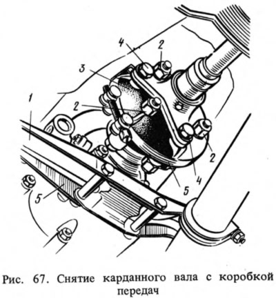
Using the 02.7812.9500 articulated socket wrench, unscrew the bolts securing the starter to the clutch housing and remove it. Disconnect the rear engine mount support from the crossmember 1 and remove the crossmember, supporting the gearbox from below. Place a support under the gearbox housing and use the A.55035 articulated wrench to unscrew the bolts securing the clutch housing, then remove the gearbox together with the clutch housing, moving it back to extract the drive shaft from the front bearing and from the driven disk hub.
When removing and installing, do not rest the end of the drive shaft on the thrust flange of the clutch pressure spring, so as not to deform the clutch connecting plates.
The gearbox is installed in the reverse order of removal. Before installation, apply a thin layer of LSC-15 (Litol-24) grease to the splined end of the drive shaft and center it with the A.70081 mandrel (see fig. 63) driven clutch disc.