
English Русский
Български
Беларускі
Український
Српски
Hrvatski
Română
Polski
Slovenský
Magyar
| Articles | Contacts | Sitemap |   
Repair and maintenance Lada Repair and maintenance Mazda Repair and maintenance Mitsubishi Repair and maintenance Toyota Repair and maintenance Land Rover Repair and maintenance Hyundai Repair and maintenance Nissan
VAZbook.ru


Main     1111   2101   2105   2106   2107   2109   2110   2115   2121  
VAZ-2101 (1970-1983) VAZ-21011 (1974-1983)
  • Main
  • «Zhiguli»
  • VAZ-21011
  • Power unit
  • Engine repair
  • Disassembling the engine

Disassembling the engine (VAZ-21011)

            0

Contents: Removal the flywheel ↓ Removal the tensioner and calming…↓
Removal the flywheel


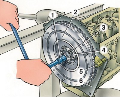
1 – key; 2 – flywheel; 3 – flywheel mounting bolt; 4 – washer; 5 – A.60330/R retainer for holding…

1 – key; 2 – flywheel; 3 – flywheel mounting bolt; 4 – washer; 5 – A.60330/R retainer for holding the flywheel from turning; 6 – Front clutch housing cover


Removal the tensioner and calming the chain
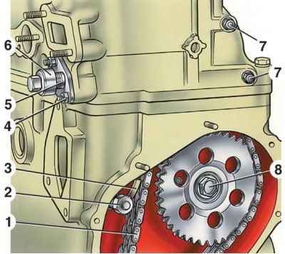


1 – camshaft drive chain; 2 – shoe mounting bolt; 3 – tensioner shoe; 4 – tensioner mounting nut; 5…

1 – camshaft drive chain; 2 – shoe mounting bolt; 3 – tensioner shoe; 4 – tensioner mounting nut; 5 – tensioner body; 6 – Tensioner cap nut; 7 – damper mounting bolts; 8 – bolt for fastening the sprocket of the oil pump drive shaft


1. Wash the engine in a washing machine, place it on a disassembly stand and drain the oil from the crankcase.

2. Remove the carburetor by disconnecting the hoses and throttle linkage from it.


3. Remove the fuel pump, ignition distributor, use key 67.7812.9514 to unscrew the spark plugs and coolant temperature gauge sensor.

4. Remove the alternator and coolant pump drive belt, remove the alternator and alternator bracket.

5. Remove the coolant pump by disconnecting the coolant supply line from the heater from the pump and the outlet manifold.

6. Remove the coolant outlet pipe and the coolant drain pipe to the heater from the cylinder head.
6. Remove the coolant outlet pipe and the coolant drain pipe to the heater from the cylinder head.


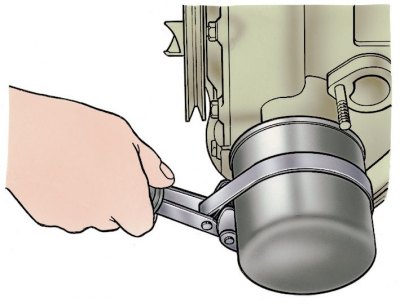
7. Using tool A.60312, unscrew and remove the oil filter with the gasket.

8. Unscrew the oil pressure warning light sensor, remove the crankcase ventilation breather cover, crankcase and oil pump. Remove the oil separator drain pipe retainer and take out the crankcase ventilation oil separator.
8. Unscrew the oil pressure warning light sensor, remove the crankcase ventilation breather cover,…


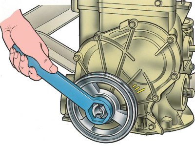
9. Remove the crankshaft pulley, securing the flywheel with the A.60330/R locking tool (see fig. Removing the flywheel) and unscrewing the ratchet with the A.50121 key.


10. Remove the cylinder head cover and the camshaft chain drive cover. Unscrew the bolts securing the camshaft sprockets and the oil pump drive shaft.

11. Loosen the cap nut 6 (see fig. Removing the tensioner and calming the chain) chain tensioner, unscrew nuts 4 securing it to the cylinder head, remove the tensioner and, having unscrewed bolt 2, remove shoe 3 of the chain tensioner.

12. Loosen the chain stop pin, remove the oil pump and camshaft drive sprockets and take out the chain.
12. Loosen the chain stop pin, remove the oil pump and camshaft drive sprockets and take out the…


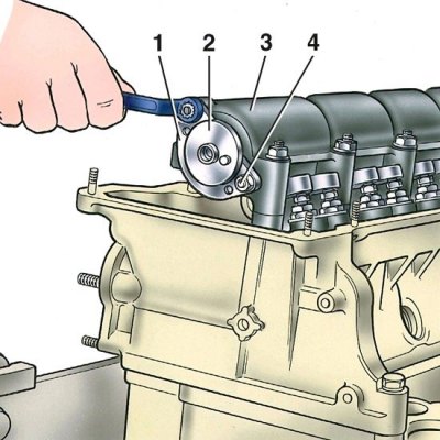
13. Loosen the nuts of studs 4. Having unscrewed the fastening nuts, remove the housing of bearings of studs 4 and, having removed the thrust flange 1, carefully, so as not to damage the surface of the supports of the housing 3 of bearings, take out the camshaft 2.

14. Loosen the cylinder head mounting bolts and remove it together with the exhaust manifold and intake manifold.
14. Loosen the cylinder head mounting bolts and remove it together with the exhaust manifold and…


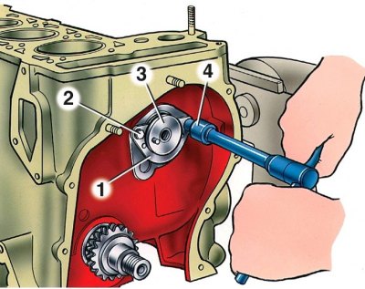
15. Remove the thrust flange 1 of the oil pump drive shaft and remove shaft 3 from the cylinder block (2 – flange mounting bolt, 4 – key).
15. Remove the thrust flange 1 of the oil pump drive shaft and remove shaft 3 from the cylinder…


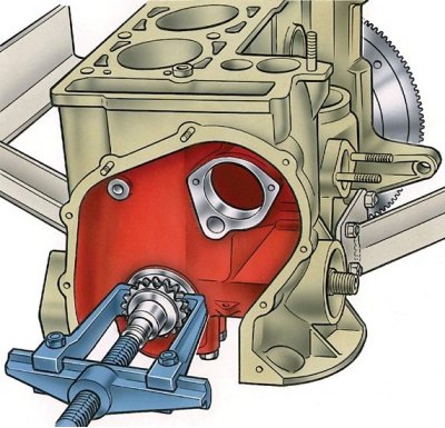
16. Using the universal puller A.40005/1/7 from the A.40005 kit, remove the sprocket from the crankshaft.

17. Loosen the connecting rod bolt nuts, remove the connecting rod caps and carefully remove the pistons with connecting rods through the cylinders.

Attention! When disassembling the engine, mark the piston, connecting rod, main and connecting rod bearing shells so that they can be installed in their original place during assembly.


18. Install lock 5 (see fig. Removing the flywheel), unscrew bolts 3, remove washer 4 and flywheel from the crankshaft, remove the front cover of the clutch housing.
18. Install lock 5 (see fig. Removing the flywheel), unscrew bolts 3, remove washer 4 and flywheel…


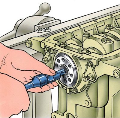
19. Using the A.40006 ejector, remove the gearbox input shaft bearing from its seat in the crankshaft.

20. Remove the crankshaft oil seal retainer.

21. Unscrew the main bearing cap bolts. Remove them together with the lower bearing shells, remove the crankshaft, upper bearing shells and thrust half rings on the rear support.


This article is available at russian, bulgarian, belarusian, ukrainian, serbian, croatian, romanian, polish, slovak, hungarian
The text was reviewed by the specialist: Grigory Vologodtsev

Share with friends:

Previous articles
VAZ-21011: Engine repair
Next articles

Removal and installation the engine
Possible engine malfunctions, their causes and methods of elimination
Features of the engine design
Engine assembly
Engine bench testing
Checking the engine on a car
Features of the cylinder block device
General cleaning and inspection of the cylinder block

More articles from other manuals on VAZ cars:
➠ Disassembling the engine VAZ-11113 (1996-2003)
➠ Disassembling the engine VAZ-2105 (1979-2010)
➠ Disassembling the engine VAZ-2115 (1997-2012)
➠ Disassembling the engine VAZ-21213 (1994-2006)
➠ The engine structure of VAZ-2106 and VAZ-2103 cars VAZ-2106 (1976-2006)
Link in different formats to this page


Visitor comments

No comments yet


How much will 11 + 21 ?


VAZ-2101 (1970-1983) 
  • General information
  • Vehicle description
  • Vehicle device
  • Vehicle operation
  • Maintenance
  • Main malfunctions
  • Applications
  • Power unit
  • Engine repair
  • Cooling and lubrication system
  • Supply system
  • Transmission
  • Clutch
  • Transmission
  • Cardan gear
  • Rear axle
  • Chassis
  • Front suspension
  • Rear suspension
  • Steering
  • Brake system
  • Body
  • Exterior
  • Interior
  • Electrical equipment
  • Engine electrics
  • Equipment and devices


VAZ-21011 (1974-1983) 
  • General information
  • Specifications
  • Operation and maintenance
  • Power unit
  • Engine repair
  • Cooling system
  • Lubrication system
  • Power and exhaust system
  • Ignition system
  • Engine electrics
  • Transmission
  • Clutch
  • Car gearbox
  • Cardan gear
  • Rear axle
  • Chassis
  • Car suspension
  • Steering
  • Brake system
  • Body
  • Exterior
  • Interior
  • Doors and locks
  • Electrical equipment
  • Equipment and devices
  • Lighting and signaling


VAZbook.ru © 2017 · Mobile version · Contact with administration · Sitemap: EN BG BY UA RS HR RO PL SK HU · Site search · News and articles VAZ-1111 · VAZ-11113 · VAZ-2101 · VAZ-21011 · VAZ-2104 · VAZ-2105 · VAZ-21051 · VAZ-2106 · VAZ-21061 · VAZ-2107 · VAZ-21099 · VAZ-2109 · VAZ-2108 · VAZ-2110 · VAZ-2112 · VAZ-2114 · VAZ-2115 · VAZ-2121 · VAZ-21213 · VAZ-21214 ·
The site stores technical data using cookies to improve the service.