
Labels on the main bearing caps and conditional number of the cylinder block
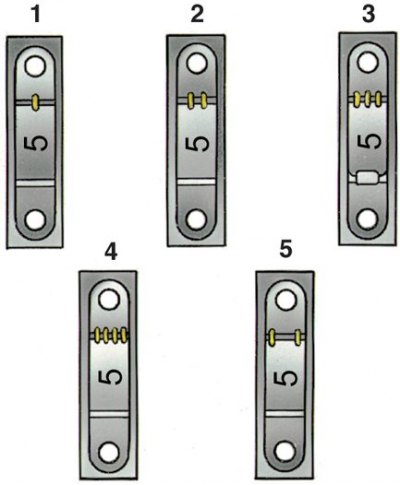
Supports are counted from the front of the engine.
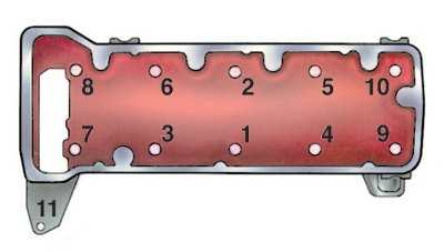
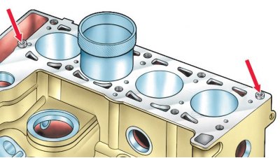
Cylinder Head Bolt Tightening Order
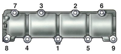
Procedure for tightening the camshaft bearing housing nuts
Checking that the alignment mark on the crankshaft sprocket matches the mark on the cylinder block
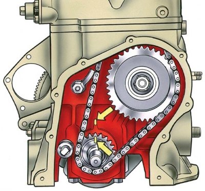
The marks are indicated by arrows.
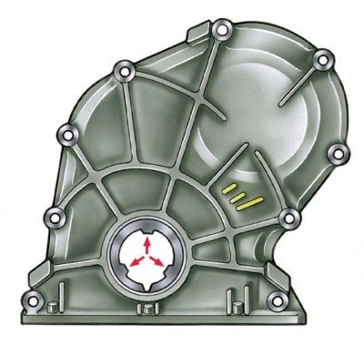
Checking that the alignment mark on the camshaft sprocket matches the mark on the bearing housing
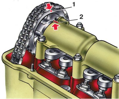
1 - mark on the asterisk; 2 - mark on the bearing housing
1. Install the washed and cleaned cylinder block on the stand and wrap the missing studs.
2. Install the washed and cleaned cylinder block on the stand and wrap the missing studs.
3. Place inserts without recess on the inner surface in the seat of the middle bearing and in its cover, and inserts with a recess in the remaining seats and corresponding covers (since 1987, the lower main bearing shells have been installed without a recess on the inner surface).
Attention! Lubricate engine cylinders, as well as pistons and seals, bearing shells and thrust half rings of the crankshaft before installation with engine oil.
4. Lay the crankshaft in the main bearings and insert two thrust half rings into the seats of the rear support, selected in thickness according to the instructions subsection 3.10.6.
5. Install the main bearing caps according to the marks (see fig. Labels on the main bearing caps and conditional number of the cylinder block).
Attention! Install the main bearing caps in the original block. For this, the cylinder block and the covers belonging to it are marked with the same reference number (see fig. Tags on the main bearing caps and the conditional number of the cylinder block and fig. Marking of the size group of cylinders on the block and conditional number of the cylinder block). Install the thrust half-rings with recesses to the thrust surfaces of the crankshaft, and place a steel-aluminum half-ring on the front side of the rear support, and a metal-ceramic half-ring on the back side (yellow color).
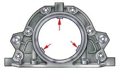
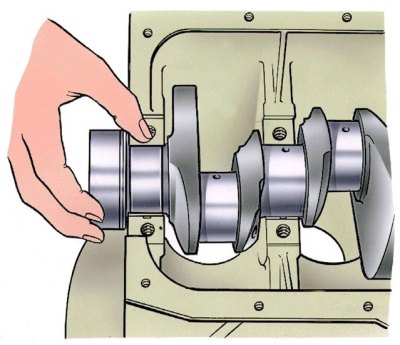
6. Put on the flange of the crankshaft the gasket of the gland holder, and insert the bolts of the front cover of the clutch housing into the sockets of the holder. Put the holder with the stuffing box on the mandrel 41.7853.4011 and, moving it from the mandrel to the crankshaft flange, attach it to the cylinder block (the arrows indicate the protrusions for centering the holder relative to the crankshaft flange).
7. Install the front cover 6 along the two centering bushes (see fig. Removing the flywheel) clutch housing.
8. Install the flywheel on the crankshaft so that the mark (cone-shaped hole) near the rim was against the axis of the connecting rod journal of the fourth cylinder, block the flywheel with the retainer A.60330 / R and bolt it to the crankshaft flange.
9. Using the bushing from A.60604 set, insert the pistons with connecting rods into the cylinders. The set contains bushings of nominal and repair sizes of pistons. Therefore, it is necessary to select a bushing suitable for the size of the piston to be installed. You can also use the adjustable sleeve 67.7854.9517.
Attention! The finger hole on the piston is offset by 2 mm, so when installing the pistons in the cylinders, the mark «P» on the pistons must face the front of the engine.
10. Install the bearings in the connecting rods and connecting rod caps. Connect the connecting rods to the crankshaft journals, install the covers and tighten the connecting rod bolts.
11. Install the sprocket on the crankshaft. Install the oil pump drive shaft and secure with the thrust flange.
12. Fit the two centering bushings on the block to the cylinder head with gasket, exhaust manifold and intake manifold.
13. Tighten in sequence (see fig. Cylinder Head Bolt Tightening Order) fastening bolts in two steps:
- pre-torque 33.3–41.16 Nm (3.4–4.2 kgf·m) bolts 1–10;
- final torque 95.94–118.38 Nm (9.79–12.08 kgf·m) bolts 1–10 and torque 31.36–39.1 N·m (3.2–3.99 kgf·m) bolt 11.
14. Rotate the flywheel so that the mark on the crankshaft sprocket aligns with the mark on the cylinder block (see pic. Checking that the alignment mark on the crankshaft sprocket matches the mark on the cylinder block).
15. Install the sprocket on the camshaft, assembled with the bearing housing, and turn the shaft so that the mark 1 on the sprocket is against the mark 2 on the bearing housing (see fig. Checking that the alignment mark on the camshaft sprocket matches the mark on the bearing housing).
16. Remove the sprocket and, without changing the position of the shaft, install the bearing housing on the cylinder head and secure by tightening the nuts in a certain sequence (see fig. Procedure for tightening the camshaft bearing housing nuts).
17. Install the chain guide on the cylinder head.
18. Install the camshaft drive chain:
- put the chain on the camshaft sprocket and insert it into the drive cavity, installing the sprocket so that the mark on it matches the mark on the bearing housing (see fig. Checking that the alignment mark on the camshaft sprocket matches the mark on the bearing housing). Do not overtighten the sprocket bolt;
- install the sprocket on the oil pump drive shaft, also without finally tightening the fastening bolt;
- install the chain tensioner shoe and tensioner without tightening the cap nut so that the tensioner spring can press the shoe; wrap the chain restrictor pin in the cylinder block;
- turn the crankshaft two turns in the direction of rotation to ensure the correct chain tension; check the alignment of the marks on the sprockets with the marks on the cylinder block (see pic. Checking that the alignment mark on the crankshaft sprocket matches the mark on the cylinder block) and on the bearing housing (see fig. Checking that the alignment mark on the camshaft sprocket matches the mark on the bearing housing).;
- if the marks match, then by blocking the flywheel with lock A.60330/R (see fig. Removing the flywheel), finally tighten the sprocket bolts, chain tensioner cap nut and bend the sprocket bolt lock washers; if the marks do not match, then repeat the chain installation operation.
19. Adjust the clearance between the camshaft cams and the valve actuating levers.
20. Install the camshaft drive cover with gasket and oil seal on the cylinder block, without finally tightening the bolts and nuts. Using mandrel 41.7853.4010, center the position of the cover relative to the end of the crankshaft and finally tighten the nuts and bolts of its fastening (the arrows show the protrusions for centering the cover relative to the crankshaft pulley hub).
21. Install the crankshaft pulley and tighten the ratchet.
22. Lubricate the oil filter o-ring with oil and install the filter by hand screwing it to the fitting on the cylinder block. Install the crankcase breather oil separator, breather cap and attach the oil separator drain tube retainer.
23. Install the oil pump and oil sump with gasket.
Install the coolant pump, alternator bracket and alternator. Put the belt on the pulleys and adjust its tension.
24. Install the heater core inlet pipe and outlet pipe on the cylinder head. Attach the heater core outlet pipe to the coolant pump and exhaust manifold.
25. Install control gauges.
26. Install the oil pump drive gear and ignition distributor. Install the ignition distributor and adjust the ignition timing. Wrap the spark plugs, install the key 67.7812.9515 on them and tighten with a torque wrench.
27. Install fuel pump (see subsection 4.1.3).
28. Install the carburetor, attach hoses to it and close it with a technological plug.
29. Install the cylinder head cover with gasket and fuel line bracket.
30. Pour oil into the filler neck on the cylinder head cover.