




View of the carburetor from the throttle drive side

1 – air damper; 2 – starting device; 3 – air damper drive lever; 4 – telescopic rod; 5 – damper control lever; 6 – lever limiting the opening of the secondary chamber throttle valve; 7 – return spring; 8 – rod connecting the primary chamber throttle valve with the starting device drive; 9 – pneumatic drive rod; 10 – pneumatic drive
Carburetor throttle body parts
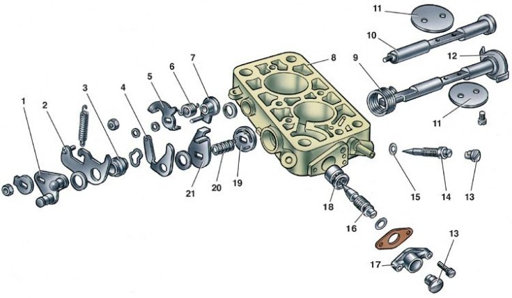
1 – damper control lever; 2 – lever limiting the opening of the secondary chamber throttle valve; 3 – bushing; 4 – air damper connection lever; 5 – lever fixed on the axis of the secondary chamber throttle valve; 6 – spring; 7 – lever connected to pneumatic drive; 8 – throttle body; 9 – primary throttle valve return spring; 10 – secondary throttle valve axis; 11 – throttle valves; 12 – primary throttle valve axis; 13 – limiting sleeve; 14 – idle mixture adjustment screw; 15 – sealing ring; 16 – mixture quantity adjustment screw; 17 – mixture quantity screw sleeve; 18 – mixing sleeve; 19 – spool; 20 – spool spring; 21 – primary chamber throttle valve axis lever
Carburetor body parts
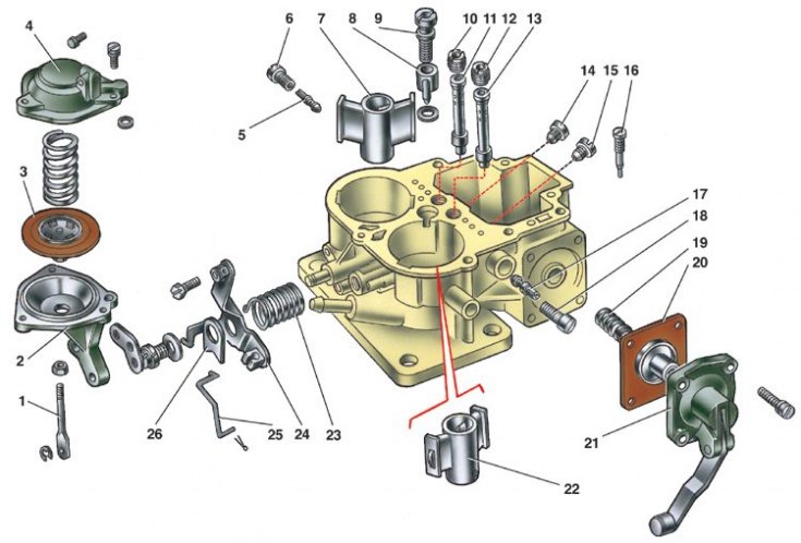
1 – secondary throttle valve pneumatic actuator rod; 2 – pneumatic drive housing; 3 – diaphragm; 4 – pneumatic drive cover; 5 – fuel jet of the secondary chamber transition system; 6 – fuel jet housing of the transition system; 7 – small diffuser; 8 – accelerator pump nozzle; 9 – accelerator pump valve screw; 10 – secondary chamber main air jet; 11 – secondary chamber emulsion tube; 12 – main air jet of the primary chamber; 13 – primary chamber emulsion tube; 14 – secondary chamber main fuel jet; 15 – main fuel jet of the primary chamber; 16 – accelerator pump adjusting screw; 17 – idle fuel jet; 18 – idle fuel jet housing; 19 – return spring; 20 – accelerator pump diaphragm; 21 – accelerator pump cover; 22 – small diffuser of the primary chamber; 23 – air damper drive lever return spring; 24 – air damper drive lever; 25 – throttle linkage rod; 26 – Throttle valve return spring bracket
1. Remove the return spring 7 (see fig. View of the carburetor from the throttle drive side) lever that limits the opening of the secondary chamber throttle valve. Unpin and disconnect rod 8 from the throttle valve lever.
2. Disconnect the pneumatic actuator rod 9 from the secondary chamber throttle actuator lever.
3. Having compressed the spring of the telescopic rod 4, disconnect it from the three-arm lever 3 of the air damper drive.
4. Remove the screws and detach the cover with the gasket from the carburetor body, being careful not to damage it or the float.
5. After unscrewing the fastening screws, detach the throttle body from the carburetor body, being careful not to damage the carburetor fuel-air channel adapter bushings and bushing seats pressed into the body. Carefully detach the heat-insulating gasket.
Carburetor cover
6. Using a mandrel, carefully push out axis 16 (see Fig. Carburetor Cover Parts) float 17 from racks (push towards the rack with a cut) and remove the axle with smooth-nosed pliers. Taking care not to damage the float tongues, remove it with the needle valve 15.
7. Remove cover gasket 11, unscrew needle valve seat 14, unscrew plug 13 and remove fuel filter 12.
8. Disconnect the telescopic rod 7 and the rod 19 of the starting device drive from the lever of the axis 8 of the air damper.
9. Unscrew the two screws securing the housing 6 of the starting device and remove it.
10. Unscrew the three screws securing cover 2 of the starting device and remove the cover with the adjusting screw 1 and spring 3.
11. Remove diaphragm 4.
Throttle body
12. Remove screw 14 (see fig. Carburetor throttle body parts) idle speed adjustment.
13. Loosen the screws securing the bushing 17 of the idle system mixture quantity screw and remove it together with screw 16.
14. Bend back the tab of the lock washer and unscrew the nut securing the levers to the primary chamber flap axis.
15. Remove the lock washer, levers 1, 2, 4 and 21 with washers and bushing 3 from the primary chamber flap shaft, and then the spool valve pressure spring 20 and spool valve 19.
16. Unscrew the nut securing the levers on the secondary chamber throttle shaft, remove levers 5, 7 with washers and spring 6.
Carburetor body
17. Remove the lever mounting screw 24 (see Fig. Carburetor body parts) air damper drive, remove lever and spring 23, disconnect rod 25 from the lever.
18. Remove the screws securing the cover 21 of the accelerator pump, remove the cover with the lever and the diaphragm 20 of the accelerator pump with the return spring 19.
19. Unscrew the main air jets 10 and 12, turn the housing over and, lightly tapping it, shake out the emulsion tubes 11 and 13 from the wells.
20. Unscrew the housings of jets 6 and 18 and remove them together with jets 5 and 17.
21. Unscrew the valve screw 9 and remove the accelerator pump sprayer 8 with gaskets, unscrew the adjusting screw 16.
22. Remove small diffusers 7 and 22.
23. Unscrew the main fuel jets 14 and 15.
24. Loosen the bracket 2 mounting screws and remove the secondary chamber throttle actuator.
25. Unscrew the three screws securing the cover 4 of the pneumatic drive and remove it, then the spring and diaphragm 3 with the rod 1.