
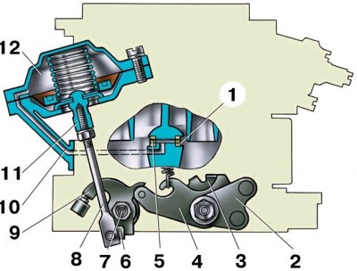
Scheme of the main dosing system of the carburetor and econostat
The econostat is located in the secondary chamber of the carburetor. In the diagram, it is conditionally shown in the primary chamber.
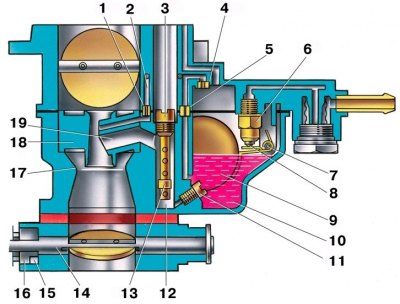
1 - emulsion jet econostat; 2 – emulsion channel of econostat; 3 - air jet of the main dosing system; 4 – econostat air jet; 5 – econostat fuel jet; 6 - needle valve; 7 - the axis of the float; 8 – a ball of a locking needle; 9 - float; 10 - float chamber; 11 - main fuel jet; 12 - emulsion well; 13 - emulsion tube; 14 - axis of the throttle valve of the primary chamber; 15 - spool groove; 16 - spool; 17 - large diffuser; 18 - small diffuser; 19 - atomizer
Scheme of the carburetor idle system
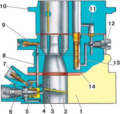
1 - throttle body; 2 - throttle valve of the primary chamber; 3 - openings of transient modes; 4 - hole adjustable with a screw; 5 - air supply channel; 6 - adjusting screw for the amount of the mixture; 7 - composition adjusting screw (quality) mixtures; 8 - emulsion channel of the idle system; 9 - adjusting screw for additional air; 10 - cover of the carburetor body; 11 - air jet of the idle system; 12 - fuel jet of the idle system; 13 - fuel channel of the idle system; 14 - emulsion well
Accelerator pump diagram
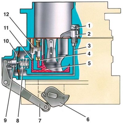
1 - screw valve; 2 - atomizer; 3 - fuel channel; 4 - bypass jet; 5 - float chamber; 6 - accelerator pump drive cam; 7 – drive lever; 8 - return spring; 9 - diaphragm cup; 10 - pump diaphragm; 11 - inlet ball valve; 12 - gasoline vapor chamber
Diaphragm Trigger Diagram
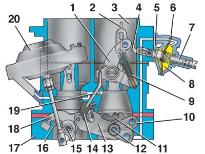
1 - air damper drive lever; 2 - air damper; 3 - air pipe of the primary chamber of the carburetor; 4 - thrust; 5 - the rod of the starting device; 6 - aperture of the starting device; 7 - adjusting screw of the starting device; 8 - cavity communicating with the throttle space; 9 - telescopic rod; 10 – damper control lever; 11 - lever; 12 - axis of the throttle valve of the primary chamber; 13 – lever on the axis of the damper of the primary chamber; 14 - lever; 15 - axis of the throttle valve of the secondary chamber; 16 - throttle valve of the secondary chamber; 17 - throttle body; 18 – throttle control lever of the secondary chamber; 19 - thrust; 20 - pneumatic actuator
Scheme of the pneumatic actuator of the throttle valve of the secondary chamber
1 – pneumatic drive jet located in the diffuser of the primary chamber; 2 – damper control lever; 3 - a lever rigidly connected to the axis of the throttle valve of the primary chamber; 4 - a lever that limits the opening of the throttle valve of the secondary chamber; 5 - pneumatic drive jet located in the diffuser of the secondary chamber; 6 - lever connected to lever 9 through a spring; 7 - axis of the throttle valve of the secondary chamber; 8 – pneumatic actuator rod; 9 – throttle control lever of the secondary chamber; 10 - channel for supplying vacuum to the pneumatic actuator; 11 - stem bushing; 12 - pneumatic throttle valve of the secondary chamber
Until 1974, carburetors 2101-1107010 were installed on VAZ-2101, -2102 cars (number cast on the bottom flange of the carburetor body). From 1974 to 1976 (inclusive) 2101-1107010-02 carburetors were used on these cars, and 2101-1107010-03 carburetors were installed from 1977 to 1980.
All these carburetors had basically the same design and differed in the diameters of some jets, and on the first two carburetors a float chamber unbalance valve was also installed.
Since 1980, the carburettor 210-1107010-20 has been used on cars (type «Ozone»). It differed from the old carburetors in the diameters of the jets, the presence of a pneumatic throttle valve of the secondary chamber and the introduction of a pipe for vacuum sampling to the vacuum regulator of the ignition distributor.
In the early 80s, the carburetor 2105-1101010-10 was also produced without a vacuum extraction pipe to the vacuum regulator of the ignition distributor. It was supplied in spare parts for installation on engines that had a P125 ignition distributor without a vacuum regulator.
This chapter describes the 2105-1107010-20 carburetor, since it was installed on most cars, and the old carburetors are no longer available.
Carburetor 2105-1107010-20 emulsion type, two-chamber, with a falling stream. The carburetor has a balanced float chamber, a crankcase exhaust system for the throttle valve.
There are two main dosing systems in the carburetor (see fig. Scheme of the main dosing system of the carburetor and econostat) primary and secondary mixing chambers, idle system (see fig. Scheme of the carburetor idle system) primary mixing chamber, secondary mixing chamber transition system, enrichment device (econostat), diaphragm accelerator pump (see fig. Accelerator pump diagram) with mechanical drive and diaphragm trigger (see fig. Diaphragm Trigger Diagram) starting a cold engine. The throttle valve of the secondary chamber is pneumatically actuated (see fig. Scheme of the pneumatic actuator of the throttle valve of the secondary chamber).
Carburetor calibration data 2105-1107010-20
Indicators | 1st camera | 2nd camera |
| Diffuser diameter, mm | 21 | 25 |
| Atomizer calibration number | 3,5 | 4,5 |
| Diameter of the main fuel jet, mm | 1,07 | 1,62 |
| Main air jet diameter, mm | 1,70 | 1,70 |
| Emulsion tube calibration number | F15 | F15 |
| Idle fuel jet diameter, mm | 0,50 | 0,60 |
| Idle air jet diameter, mm | 1,70 | 0,70 |
| Accelerator pump nozzle diameter, mm | 0,40 | – |
| Accelerator pump bypass jet diameter, mm | 0,40 | – |
| Performance of the accelerating pump for 10 full strokes, cm3 | 7 ± 25% | |
| Econostat fuel jet diameter, mm | – | 1,50 |
| Econostat air jet diameter, mm | – | 1,20 |
| Econostat emulsion jet diameter, mm | – | 1,50 |
| Launcher air jet diameter, mm | 0,70 | |
| Float distance from carburetor cover with gasket, mm | 6,5 ± 0,25 | |