
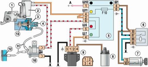
Forced idle economizer system (EPHH): 1 - throttle actuator lever; 2 - microswitch; 3 - economizer; 4 - mixture quantity screw; 5 - mounting block of relays and fuses; 6 - ignition relay; 7 - ignition switch; 8 - ignition coil; 9 - electropneumatic valve control unit; 10 - electropneumatic valve; 11 - hoses; 12 - inlet pipeline; 13 - economizer valve needle
The idle system is designed to supply fuel to the throttle space of the primary chamber and turn off its supply in the forced idle mode (engine braking). The system consists of an economizer, a microswitch, an electro-pneumatic valve and an electro-pneumatic valve control unit. The economizer, together with the microswitch bracket, is attached with two screws to the throttle body. When the ignition is off, the needle of the economizer valve closes the fuel supply channel. The needle is made integral with the diaphragm rod and when a vacuum is created in the post-diaphragmatic space, it moves and opens the channel. The stroke of the needle and, accordingly, the fuel consumption through the idle system is regulated by a screw ("quantities"). Vacuum is supplied to the economizer from the inlet pipeline through hoses through an electro-pneumatic valve installed on the right mudguard in the engine compartment of the vehicle. The electropneumatic valve is controlled by a control unit and a microswitch. The electropneumatic valve control unit is located on the left mudguard in the engine compartment. The control unit, depending on the control pulses coming from the primary winding of the ignition coil, turns off the electro-pneumatic valve when the microswitch contacts are open and the engine speed is 1600 rpm and turns it on again when the speed drops to 1200 rpm. The microswitch opens the voltage supply circuit to the electro-pneumatic valve when the pedal is released "gas". When the engine speed is more than 1600 rpm and the pedal is released "gas" fuel supply through the idle channel is stopped.