




Contents: Disassembly ↓ Assembly ↓
We disassemble the carburetor body to wash its parts, clean the channels, replace defective parts, gaskets and diaphragms. The body consists of a large number of small parts, so its disassembly must be carried out on a clean surface where you can lay out the parts without mixing them up.
To carry out the work you will need carburetor cleaner or acetone.
Disassembly
1. Remove the carburetor (see "Carburetor - removal and installation").
2. Disconnect the carburetor cover from the body (see "Carburetor cover - removal and disassembly").
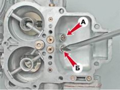
3. Using a slotted screwdriver, unscrew the main fuel jet A of the secondary chamber marked "150" and the main fuel jet B of the primary chamber marked "112".
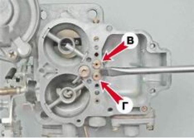
4. Using the same tool, unscrew the main air jet B of the secondary chamber marked "130" and the main air jet G of the primary chamber marked "150".
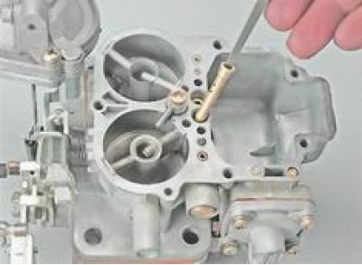
5. Emulsion tubes are installed under the air jets in the wells. Using a suitable tool, we remove them from the wells. For this operation, you can use a file with a tapering working surface.
6. Using a slotted screwdriver, unscrew the accelerator pump valve screw.

7. Remove the valve with the accelerator pump sprayer and sealing ring. Using a thin screwdriver, remove the lower sealing ring from the hole.
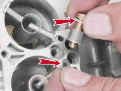
8. Using pliers, remove the small diffusers of the primary B and secondary A chambers. The primary chamber diffuser is marked 3.5 (35), and the secondary chamber is marked 4.5 (45).
If the diffusers cannot be removed after removing the throttle body (see below), knock them out from the opposite side using a soft metal punch.
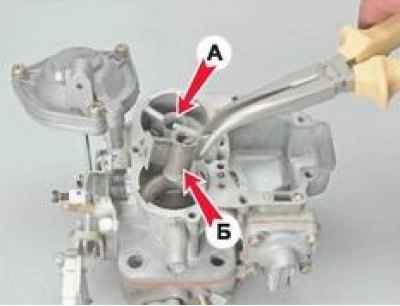
9. Using a slotted screwdriver with a blade width of no more than 3 mm, unscrew the accelerator pump screw and remove it from the channel.
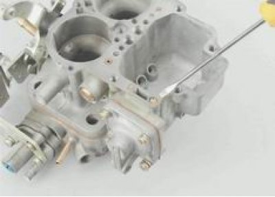
10. Using a slotted screwdriver, unscrew the housing of the fuel jet of the secondary chamber transition system.
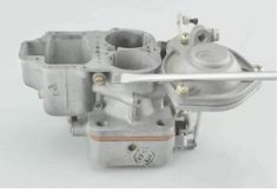
11. Remove the housing with the jet from the channel.
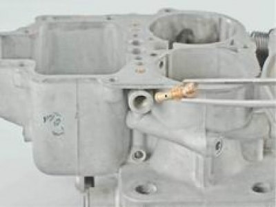
12. Remove jet B from body A.

13. Using a slotted screwdriver, unscrew the housing of the idle system fuel jet.
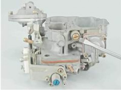
14. Remove the body with the jet from the channel opening.
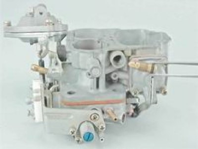
15. Remove jet A from body B and, using a screwdriver, remove rubber sealing ring B from the body.
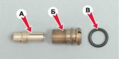
The damaged ring must be replaced.
16. Using a Phillips screwdriver, unscrew the four screws securing the accelerator pump diaphragm cover.
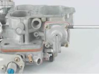
17. Remove the cover, take out the spring and disconnect the diaphragm.
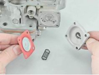
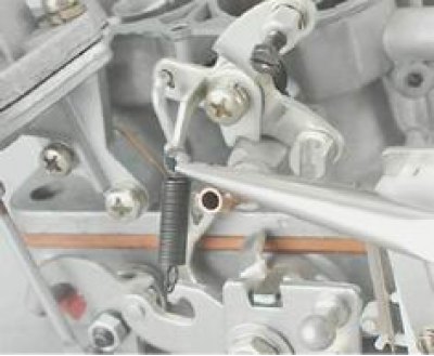
18. Using pliers, disconnect and remove the return spring.
19. Disconnect the throttle valve pneumatic drive (see "Pneumatic throttle actuator - removal and installation").
20. Using a Phillips screwdriver, unscrew the two screws securing the throttle body to the carburetor body.
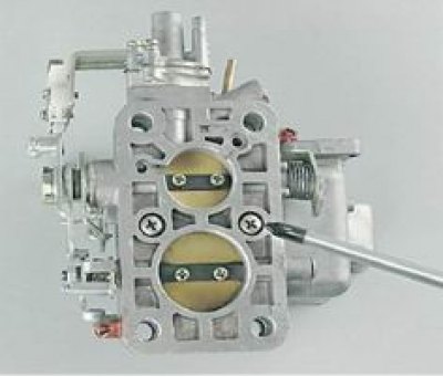
21. We separate the housings by disengaging rod A from the lever.
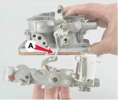
22. Carefully remove the heat-insulating spacer with two cardboard gaskets.
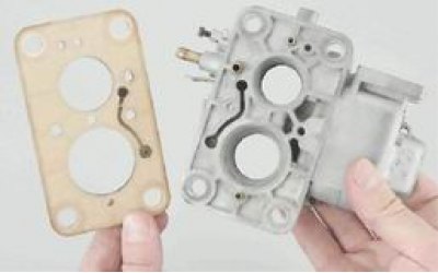
23. Remove the microswitch with the bracket and the economizer (see "Forced Idle Economizer [FIE] - Checking and Replacing").
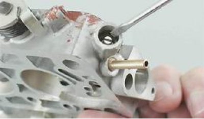
24. Using a slotted screwdriver, unscrew and remove the quality screw with a rubber sealing ring. For ease of subsequent installation, remember the number of turns of the screw.
Note: If the screw has a limiting sleeve installed, use a slotted screwdriver to turn the sleeve until it breaks and remove its parts from the hole.
Assembly
1. Before assembly, wash the carburetor parts with a cleaner or acetone. Blow out the fuel and air channels with compressed air. Check the condition of the gaskets: breaks and cracks are not allowed. If necessary, replace the gaskets with new ones. When assembling, lubricate all rubber sealing rings with engine oil. Assemble the carburetor body in the reverse order.
2. Install previously removed parts in the reverse order.