




Contents: The deformation of the lower arm is…↓ Condition of rubber-metal hinges ↓ Clearance in upper ball joints ↓ Condition of lower ball joints ↓
During each maintenance and repair, check the condition of the protective covers of the suspension ball joints, paying special attention to the absence of mechanical damage. Find out if there are any cracks or traces of contact with road obstacles or the body on the suspension parts, deformations of the steering knuckle, the axis of the lower arm, the suspension arms and the elements of the front of the body, and also check the gap in the upper ball joint and the condition of the lower ball joint.
The deformation of the lower arm is determined by inspection
Check the deformation of the front suspension cross member in the following sequence:
- unscrew the axle mounting nuts 35 (see fig. 156) lower levers so that the resulting gap between washer 28 and the mating surface of cross member 30 fits the leg of the caliper tightly against the bolt rod;
- measure the length of the cross member between the planes of the lower arm axes (left and right) in the area of the front bolts. The distance should be 611±1 mm. Replace the crossbar if it is deformed so that the wheel alignment angles cannot be adjusted.
Condition of rubber-metal hinges
Check the condition of the rubber-metal joints in the following order:
- after making sure that there is no deformation of the suspension arms or the lower arm axle, lift the front wheels of the vehicle;
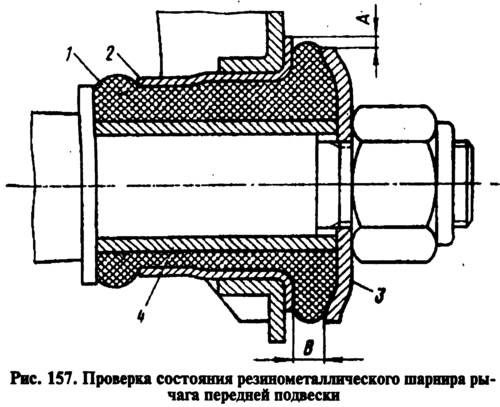
- measure the radial offset A (Fig. 157) of the outer bushing 2 relative to the inner bushing 4 and the distance B between the thrust washer 3 and the outer end of the outer bushing 2. Replace the rubber-metal hinges if it is impossible to adjust the wheel camber (when all washers are removed from under the lower arm axle), in case of breaks and one-sided "bulging" of rubber 1, in case of radial displacement A over 2.5 mm and if dimension B does not fit within the limits of 3-7.5 mm for the lower arm and 1.5-5 mm for the upper arm. If dimension B is outside the specified limits, check the correctness of pressing the rubber-metal hinge into the arm socket.
Clearance in upper ball joints
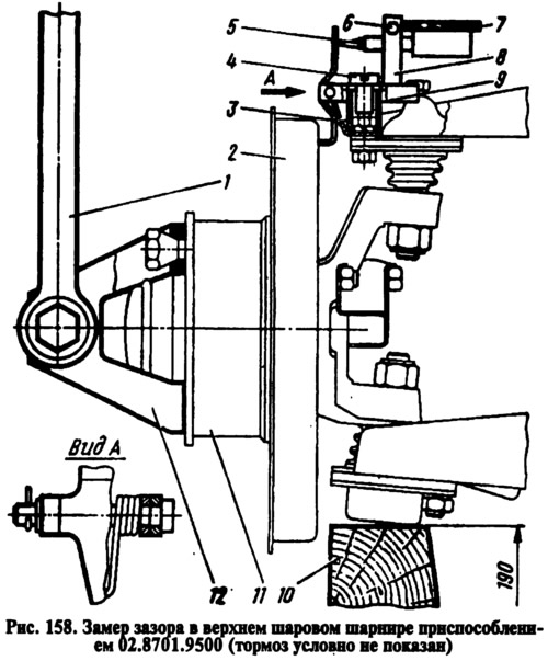
Check the clearance in the upper ball joints using the 02.8701.9500 device. To do this, place the car on a flat, horizontal surface with a hard surface, lift the front of the car and remove the wheel. Place a wooden block 10 (Fig. 158) 190 mm high under the lower ball joint and lower the car onto it. Install sleeve 9 on the nut of the upper hinge mounting bolt closest to the casing, then put base 8 on the sleeve and lightly secure it with screw 4. Moving the device, set lever 3 in a vertical position so that its lower end rests against protective casing 2 of the brake, and tighten screw 4. Install indicator 7 in the stand of base 8 until its leg 5 stops in lever 3 with an interference of 2-3 mm and tighten bolt 6. Attach bracket to hub 11 with two bolts, put torque wrench 1 on the hexagonal head of bracket axle 12 and turn the key towards and away from the car with a torque of 20 kgf·m. Add up both indicator readings. The sum should not exceed 0.8 mm.
Condition of lower ball joints
Check the condition of the lower ball joints in the following order:
- place the car on a flat, level surface with a hard surface and lift the front of the car, then remove the wheel;
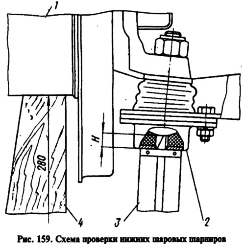
- place a wooden block 4, 280 mm high, under hub 1 (Fig. 159) and lower the vehicle onto it;
- clean the lower part of the joint 2 from dust and dirt and unscrew the conical plug;
- measure the distance H with a depth gauge of a caliper 3. If H > 11.3 mm, then remove the joint from the car and inspect it carefully. There should be no cracks on the joint housing, and no dirt in the grease. If there is dirt in the grease, cracks in the housing, or if N > replace the 11.8 mm hinge.
Check the condition of the front body elements as indicated in the section "Body".
The text is copied from the online resource: VAZbook.ru