
English Русский
Български
Беларускі
Український
Српски
Hrvatski
Română
Polski
Slovenský
Magyar
| Articles | Contacts | Sitemap |   
Repair and maintenance Lada Repair and maintenance Mazda Repair and maintenance Mitsubishi Repair and maintenance Toyota Repair and maintenance Land Rover Repair and maintenance Hyundai Repair and maintenance Nissan
VAZbook.ru


Main     1111   2101   2105   2106   2107   2109   2110   2115   2121  
VAZ-2121 (1977-1994) VAZ-21213 (1994-2006) VAZ-21214 (1994-2006)
  • Main
  • «Niva»
  • VAZ-21213
  • Chassis
  • Wheel suspension
  • Determining the condition of the front suspension parts

Determining the condition of the front suspension parts (VAZ-21213)

            0

During each maintenance, as well as during repairs, it is necessary to check the condition of the protective covers of the ball joints of the suspension, paying special attention to the absence of mechanical damage to the covers. It is necessary to carefully inspect the suspension parts, checking for traces of contact with road obstacles or the body, for cracks in the suspension parts, deformations of the axles of the lower arms, cross members or suspension arms and elements of the front of the body, and also check the condition of the ball and rubber-metal joints.

Deformation of the lower and upper arm axes determined by inspection.

Deformation of the front suspension cross member is determined by measuring the distance between the outer surfaces of the crossbar brackets in the area of the upper arm axle mounting bolts. This distance should be (736+1.5) mm.

If the cross member is deformed so that it is impossible to adjust the wheel alignment angles with washers while all suspension elements are in satisfactory condition, replace the cross member.

The condition of rubber-metal hinges is checked in the following order:
  • make sure there is no deformation of the suspension arms, lower arm axle, or suspension cross member; jack up the front wheels of the car;
  • make sure there is no deformation of the suspension arms, lower arm axle, or suspension cross member; jack up the front wheels of the car;
  • measure the radial displacement A (Fig. 4-2) of the outer sleeve 2 relative to the inner sleeve 6 and the distance B between the thrust washer 5 and the outer end of the outer sleeve 2.
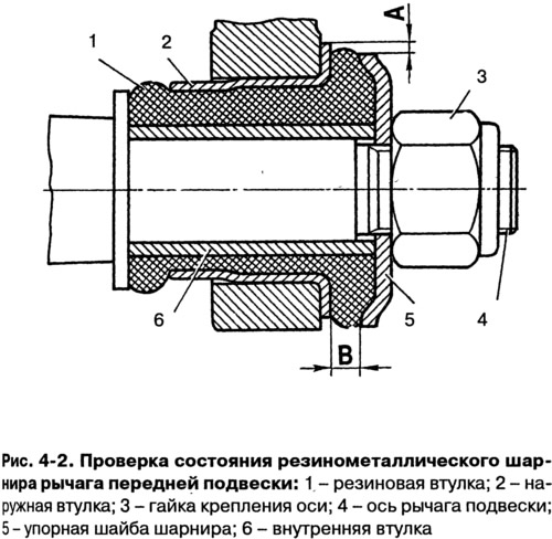

measure the radial displacement A (Fig. 4-2) of the outer sleeve 2 relative to the inner sleeve 6…


The rubber-metal joints of the upper and lower arms are subject to replacement:


  • in case of ruptures and one-sided "bulging" of rubber;
  • when cutting and wearing out the rubber on the ends of the hinges;
  • if the radial displacement A of the outer sleeve relative to the inner one exceeds 2.5 mm;
  • if size B does not fit within the range of 3-7.5 mm.

If dimension B is outside the specified limits, check that the rubber-metal joint is pressed into the lever socket correctly.

Checking the clearance in the upper ball joints is carried out in the following order:
  • place the vehicle on a level, horizontal surface with a hard surface;
  • lift the right (left) front of the car and remove the wheel;
  • place a 230 mm high wooden block under the lower arm, closer to the ball joint, and lower the car onto it;
  • make sure that the resin does not protrude from the sprue hole of the upper ball pin housing, if necessary, clean it with a file to avoid errors in measurement;
  • secure bracket 4 (Fig. 4-3) of the device indicator to the upper end of the steering knuckle;
  • install indicator 2 in the center of the sphere of the body 3 of the ball joint of the pin with a slight preliminary compression, and then align the zero division of the indicator scale with the arrow;
  • attach a 0.7 m long fork arm 5 to the upper arm of the front suspension;
  • apply a load of 196 N·m (20 kgf·m) in the vertical direction using a torque wrench6 (at the end of the fork lever 294 N) first by pressing in and then by pulling out the ball pin from the joint housing;
  • record the corresponding maximum deviations of the indicator arrow;
  • calculate the value of the gap in the upper ball joint by adding up the values of deviations from the zero position;
  • the total indicator readings should not exceed 0.8 mm.
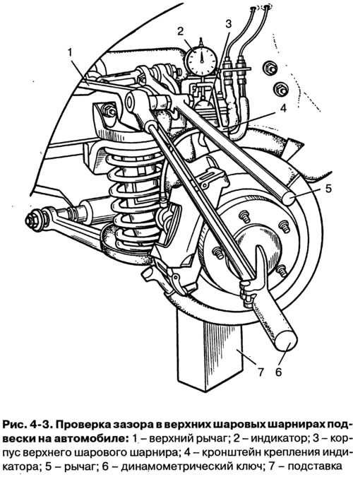
the total indicator readings should not exceed 0.8 mm.


This article is available at russian, bulgarian, belarusian, ukrainian, serbian, croatian, romanian, polish, slovak, hungarian
The text was reviewed by the specialist: Grigory Vologodtsev

Share with friends:

Previous articles
VAZ-21213: Wheel suspension
Next articles

Front suspension device
Possible suspension faults, their causes and methods of elimination
Checking and adjusting the front wheel alignment angles
Checking and adjusting the clearance in the front wheel hub bearings
Replacing grease in front wheel hub bearings
Removal and installation the front suspension
Disassembly and assembly of front suspension units

More articles from other manuals on VAZ cars:
➠ Determining the condition of the front suspension parts VAZ-21011 (1974-1983)
➠ Determining the condition of the front suspension parts on a… VAZ-2105 (1979-2010)
➠ Checking the condition of the front and rear suspension parts VAZ-1111 (1988-1996)
➠ Front suspension — technical condition check VAZ-2106 (1976-2006)
➠ Front suspension — technical condition check VAZ-2107 (1982-2012)
Link in different formats to this page


Visitor comments

No comments yet


How much will 48 + 29 ?


VAZ-2121 (1977-1994) 
  • General information
  • Vehicle device
  • Car VAZ-21219
  • Power unit
  • Engine repair
  • Cooling system
  • Lubrication system
  • Supply system
  • Transmission
  • Clutch
  • Car gearbox
  • Transfer case
  • Cardan gear
  • Rear axle and gearbox
  • Front axle
  • Chassis
  • Front suspension
  • Rear suspension
  • Steering
  • Brake system
  • Body
  • Exterior
  • Interior
  • Doors and windows
  • Electrical equipment
  • Equipment and devices
  • Headlights and lighting
  • Engine electrics


VAZ-21213 (1994-2006) 
  • General information
  • Vehicle device
  • User manual
  • Power unit
  • Engine repair
  • Cooling and lubrication system
  • Supply system
  • Transmission
  • Clutch
  • Car gearbox
  • Transfer case
  • Cardan gear
  • Rear axle and shafts
  • Front axle and wheel drive
  • Chassis
  • Wheel suspension
  • Steering
  • Brake system
  • Body
  • Exterior
  • Interior
  • Electrical equipment
  • Engine electrics
  • Equipment and devices


VAZ-21214 (1994-2006) 
  • General information
  • Vehicle information
  • Troubleshooting
  • Power unit
  • Engine repair
  • Cooling system
  • Fuel system (carburetor)
  • Fuel system (injector)
  • Ignition system
  • Control system
  • Exhaust system
  • Transmission
  • Clutch
  • Car gearbox
  • Transfer case
  • Cardan gear
  • Front axle
  • Rear axle
  • Chassis
  • Front suspension
  • Rear suspension
  • Steering
  • Brake system
  • Body
  • Exterior
  • Interior
  • Doors, covers and windows
  • Ventilation and heating
  • Electrical equipment
  • Equipment and devices
  • Headlights and lighting
  • Engine electrics
  • Electrical circuits


VAZbook.ru © 2017 · Mobile version · Contact with administration · Sitemap: EN BG BY UA RS HR RO PL SK HU · Site search · News and articles VAZ-1111 · VAZ-11113 · VAZ-2101 · VAZ-21011 · VAZ-2104 · VAZ-2105 · VAZ-21051 · VAZ-2106 · VAZ-21061 · VAZ-2107 · VAZ-21099 · VAZ-2109 · VAZ-2108 · VAZ-2110 · VAZ-2112 · VAZ-2114 · VAZ-2115 · VAZ-2121 · VAZ-21213 · VAZ-21214 ·
The site stores technical data using cookies to improve the service.