




The suspension guide device is made on four transverse swing arms 13 and 36 (Fig. 156), to which two steering knuckles are pivotally attached using ball joints 14 and 45. The upper suspension arm 13 is connected by an axle to the front pillar of the body, and the lower arm 36 is suspended by means of an axle 35 on bolts 37 to the suspension crossmember 30. The latter in turn is attached by means of a bracket 29 to the body side members. Distance 28 and adjusting 27 washers are installed between the axle of the lower arm and the crossmember. By changing the number of washers 27, the longitudinal inclination of the steering axis and the camber of the front wheels are adjusted. Both suspension arms are connected to the axles via rubber-metal hinges, ensuring a gap-free connection of these parts.
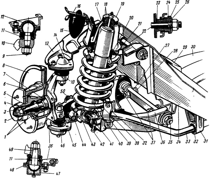
Fig. 156. Front suspension:
1 - Front wheel hub bearings; 2 - hub cap; 3 - adjusting nut; 4 - washer; 5 - steering knuckle journal; 6 - wheel hub; 7 - oil seal; 8 - brake disc; 9 - ball pin of the upper support; 10 - steering knuckle; 11 - Ball joint protective cover; 12 - Upper support bearing; 13 - Upper suspension arm; 14 - upper support bearing housing; 15 - compression stroke buffer; 16 - compression stroke buffer bracket; 17 - shock absorber support cup; 18 - shock absorber mounting pads; 19 - pillow washer; 20 - suspension spring insulating gasket; 21 - Upper support cup of suspension spring; 22 - Upper suspension arm axle; 23 - inner sleeve of the hinge; 24 - outer sleeve of the hinge; 25 - rubber bushing of the hinge; 26 - support washer; 27 - adjusting washers; 28 - spacer washer; 29 - bracket for fastening the cross member to the body side member; 30 - Front suspension crossmember; 31 - stabilizer bar mounting bracket; 32 - stabilizer bar cushion; 33 - stabilizer bar; 34 - body side member; 35 - lower arm axle; 36 - lower suspension arm; 57 - lower arm axle mounting bolts; 38 - suspension spring; 39 - stabilizer bar mounting clip; 40 - shock absorber; 41 - shock absorber mounting bolt; 42 - shock absorber mounting nut to suspension arm; 43 - shock absorber mounting bracket to lower suspension arm; 44 - lower support cup; 45 - lower support liner collar; 46 - lower support bearing housing; 47 - Ball pin cage insert; 48 - lower support bearing; 49 - ball pin; 50 - front wheel turning limiter.
The elastic element of the suspension is a cylindrical spring 38, whose upper end rests through a support cup 21 with a rubber gasket 20 on the body front pillar. The lower end of the spring rests on the support cup 44 of the lower arm.
The lateral roll of the body when turning the car is reduced by the anti-roll bar, made in the form of a rod 33 made of spring steel. The wheel hub 6 is mounted on the pivot pin of the steering knuckle on two tapered roller bearings 7, which are pressed by an adjusting nut 3. On the inside, a self-tightening oil seal is installed in the hub socket, and on the outside, the hub cavity is closed by a cap 2. The brake disc 8 and the pressure ring are fastened to the hub flange with two guide pins, and the wheel disc is fastened with bolts.
The damping elements of the suspension - shock absorbers - are described below.