
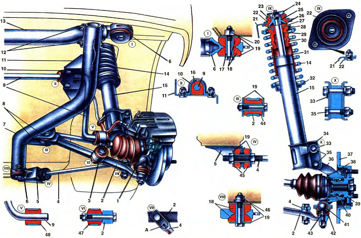
1. Suspension arm ball joint. 2. Lower suspension arm. 3. Anti-roll bar. 4. Stretching. 5. Bracket subframe for attaching extensions. 6. Eyelet subframe. 7. Spar subframe. 8. Bracket subframe for attaching the suspension arm. 9. Anti-roll bar. 10. Clip. 11. Subframe bracket for attaching the stabilizer bar. 12. Bolts for fastening the left side member of the subframe. 13. Front cross member of the subframe. 14. Suspension spring. 15. Front suspension strut. 16. Stabilizer bar cushion. 17. Spacer sleeve. 18. Rubber bushings for mounting the subframe. 19. Thrust washers. 20. Body weld nut for attaching the subframe. 21. Rack mudguard body. 22. The body of the upper support. 23. Rubber part of the upper support. 24. The upper clip of the support. 25. The lower clip of the support. 26. Thrust washer of the plain bearing. 27. Sealing ring bearing. 28. Upper spring cup. 29. Bearing sleeve. 30. Buffer compression stroke. 31. Protective cover. 32. The lower support cup of the suspension spring. 33. Bolt eccentric. 34. Terminal bracket suspension strut. 35. Bolts for attaching the suspension strut to the steering knuckle. 36. Swivel fist. 37. Disc brake. 38. Dirt ring. 39. Front wheel hub. 40. Wheel bearings. 41. Ball joint bearing. 42. Protective cover of the ball joint. 43. Ball pin. 44. Rubber-metal hinge suspension arm. 45. Pillow for attaching stretch marks. 46. Welded bushing of the body for attaching the subframe. 47. Rubber-metal hinge of the stabilizer bar. 48. Rubber bushing of the stabilizer bar.
A - label
Front suspension independent, type «rocking candle» (McPherson), aggregated together with the power unit and steering on the subframe. The suspension is compact and simple, pairing well with the rack and pinion steering and transverse powertrain.
The layout of the front suspension and the specific design of a number of its units create a negative rolling shoulder when the point of intersection of the wheel turning axis with the roadbed lies outside the outer part of the vehicle track. The negative shoulder of the roll creates conditions for the use of a diagonal drive of the brake mechanisms of the wheels, in which the likelihood of the vehicle skidding during braking is practically excluded. This improves driving safety.
The front suspension is the link between the body and the front wheels. Through the elements of the front suspension, the forces acting on the wheels are transmitted to the body. The components included in the front suspension soften dynamic loads, reduce body vibrations, provide good stability and smoothness of the car.
The sub-assembly, which includes the power unit with wheel drives, front wheel brakes, steering gear and front suspension, pre-adjusted on a special device, is mounted from below when assembling the car on the conveyor.
The subframe assembly with mounted units and assemblies is attached to the body at four points with bolts with support washers 19 through rubber bushings 18. The subframe fastening bolts are wrapped in weld nuts 20 and bushings 48 of the body.
The subframe consists of two longitudinal spars 7 and a front cross member 13 made of pipes. They are interconnected: the right spar and cross member by welding, the left spar and cross member - with bolts 12. Support 5 is bolted to the rear of the side members (see ch. 26) steering mechanism. Bolted connection of the left side member with a cross member 13 (see ch. 23) and steering gear support 5 (see ch. 26) allows you to remove the gearbox from the car without removing the entire subframe with the units and assemblies installed on it.
The following are welded to the spars of the subframe: brackets 11 for attaching the stabilizer bar 9, brackets 8 for attaching suspension arms, brackets 5 for attaching braces 4, and brackets for attaching the power unit. Eyelets 6 are welded at the ends of the cross member 13 and at the rear of the spars for attaching the subframe to the body.
The suspension consists of a guiding device, elastic and damping elements.
The suspension guide determines the nature of the movement of the wheels relative to the body, and also transfers forces and moments from the wheels to the body. The guide device includes the lower arm 2 with extension 4, the telescopic strut 15 and the knuckle 36 connecting the strut and the lever to each other. The guide device also includes the bar 9 of the anti-roll bar.
The lower V-shaped suspension arm is formed by a transverse forged arm 2 and an extension 4 from a bar directed backwards. The extension is connected to the transverse lever with a bolt in one position, in which mark A (edge) stretched upwards. The other end of the extension is connected to the front bracket 5 of the subframe by means of two nuts and rubber pads 45 with thrust washers 19. By moving the extension, carried out by screwing or folding the nuts of its fastening, the longitudinal inclination of the axis of rotation is regulated.
When the suspension moves, the lever 2 rotates within the elastic deformation of the rubber-metal hinge 44 and rubber pads 45. In this case, turning the rubber-metal hinge in the lever socket or its bushings relative to each other is not allowed.
The telescopic rack 15 of the suspension is double-pipe, double-acting, with a variable fluid flow. The telescopic rack combines the functions of a carrier and guiding device, as well as a damping element in one unit.
The upper part of the rack 15 is fixed in the rack 21 of the mudguard of the body with two self-locking nuts through a highly elastic support 22. The design of the upper support provides «rocking» racks during its telescoping and good damping of high-frequency vibrations transmitted by tires to the body. The rotation of the rack when turning the wheels is provided by a plain bearing (pos. 26, 29), located in the upper support 22.
The lower part of the rack 15 is connected to the steering knuckle 36 by means of a terminal bracket 34 with an eccentric device for adjusting the camber of the front wheels.
On the telescopic rack are installed: coil spring 14, polyurethane foam buffer 30 compression stroke (elastic suspension elements) and upper support assembly with plain bearing and fastening bolts. The suspension spring is installed between the top 28 and bottom 32 support cups. The lower cup 32 is welded to the suspension strut, the upper 28 is attached together with the support on the strut rod. The compression stroke buffer 30 is installed on the rod assembly with a protective cover 31, which protects the rod from mechanical damage.
Spring 14 is made of special spring steel and, depending on the length under a control load, is divided into two classes: A and B. Class A springs are marked with yellow paint on the outside of the middle coils, and class B is green.
The compression stroke buffer 30 limits the compression stroke of the suspension. At the moment of restriction, the buffer support pressed onto the body of the telescopic rack rests against it. The buffer is made of fine-mesh polyurethane, on the outer surface it has two annular grooves that determine the place of buffer deformation. A polyethylene protective casing 31 enters the third lower annular groove.
The upper support provides an elastic connection of the rack with the body and is one of the points relative to which the wheel axle rotates. The support consists of a body 22, to the surface of which a rubber bushing 23 is vulcanized. Two bolts for fastening the upper support are pressed into the support body and then welded. The rubber part of the support housing is clamped on the rod with a nut between the lower 25 and upper 24 support clips.
The plain bearing consists of a plastic sleeve 29, on the upper end of which there is a layer of Teflon fabric, and a thrust washer 26 adjacent to this fabric. The bearing bush is installed in the upper spring cup. The contact surface of the sliding pair is protected from dirt by a rubber sealing ring 27 sandwiched between the bearing thrust washer and the spring support cup.
Despite the short base of the car, an anti-roll bar is used to dampen lateral rolls. It is made in the form of a rod 9, which is attached to the brackets 11 of the subframe with clips 10 with rubber cushions 16. The ends of the rod through short racks 3 are connected to the suspension arms 2. The heads of the struts are pressed in: in the upper head - a rubber bushing 48, in the lower one - a rubber-metal hinge 47. A stabilizer bar passes through the upper head of the strut, and the lower head is bolted to the suspension arm 2.
The lower end of the suspension arm is connected by means of a ball joint 1 to the steering knuckle 36. The pin 43 of the ball joint enters the conical hole of the arm 2 and is fastened with a self-locking nut.
The ball joint consists of a one-piece housing, in which bearing 41, made of low-friction Teflon fabric, is filled with a special resin. It covers the ball head of the pin 43. The inner cavity of the hinge is sealed with a protective reinforced cover 42. When assembling the hinge, the ShRB-4 lubricant is put into the cover, designed for the entire service life of the car, provided that the protective cover is sealed. The hinge housing is attached from below with two bolts to the steering knuckle.
The upper part of the steering knuckle is attached to the telescopic strut bracket with two bolts 35. The upper bolt has an eccentric 33, which abuts against the flanging of the bracket cheek, and the cylindrical part of the bolt passes through the oval hole of the bracket and the cylindrical hole of the steering knuckle. This mount allows the steering knuckle to move relative to the strut bracket when the top bolt is turned, which allows you to adjust the camber of the front wheels.
In the cavity of the steering knuckle, a double-row ball bearing 40 of a closed type is installed with «eternal lubrication». It is fixed in the steering knuckle with two retaining rings. The hub 39 of the front wheel rotates on this bearing, which is connected with the spline to the shank of the wheel drive hinge housing. The hub is attached to the shank with a nut, under which a thrust washer is installed. Outside, the cavity of the hub is closed with a cap. From the inside, the cavity of the steering knuckle is protected from contamination by a dirt-reflecting ring 38., which enters the annular groove of the fist, forming a labyrinth seal. The brake disc 37 is attached to the wheel hub flange with two bolts.
In the course of compression, when the wheel of the vehicle moves upward, the suspension spring 14 is compressed by telescoping the strut. The lower arm 2 of the suspension, together with the extension 4, rotates in its hinges. This changes the angle of inclination of the telescopic strut and at the same time the hydraulic element of the strut is activated, absorbing the vibration energy. The compression stroke buffer 30 then comes into action, abutting against the suspension strut support.
During the recoil force of the spring 14, the wheel of the car moves down, the suspension strut is stretched and at the same time its angle of inclination changes. When the rack is stretched, the hydraulic element of the rack is also activated. «rocking» rack during its telescoping occurs due to the deformation of the rubber part 23 of the upper support. When the suspension arm is moved, twisting occurs (unwinding) rod 9 stabilizer, working as a torsion bar. The bar creates the most resistance in the direction of body roll, thereby reducing its tilt.
Vehicle stability, front tire wear and fuel consumption are highly dependent on the front wheel alignment. There are the following wheel alignment angles.
Camber is the tilt of the wheels in a vertical plane relative to the center line of the car. Camber can be positive if the wheels are tilted outward, or negative if the wheels are tilted inward. The camber angle mainly affects the wear uniformity of the front tire tread. When it is broken, there is increased wear on the inner or outer tracks of the tread. The camber is adjusted with the upper bolt 35 with the nuts of the steering knuckle bolts loosened.
Toe-in is the position of the front wheels when the distance between the inner flanges of the wheel rims is smaller at the front than at the rear. The distance is measured at the wheel axle level. Normal wheel alignment improves vehicle stability and reduces tire wear. The convergence is regulated by changing the length of the steering rods. In a front-wheel drive car, toe-in is close to zero, as the traction forces applied to the wheels tend to bring the wheels in front.
The angle of the longitudinal inclination of the axis of rotation. The axle about which the wheel turns has such an inclination that the upper part of the axle is tilted backwards. Such an angle of inclination of the axis is called positive, in contrast to the negative, in which the upper part of the axis is tilted forward. With a positive value of the angle, the self-return of the wheels to the middle position after the turn is improved, with a negative value, it worsens. The angle of the longitudinal inclination of the axis of rotation is regulated by the brace nuts 4 with the nut fastening the brace to the lower suspension arm loosened. To reduce the angle of longitudinal inclination, the nuts are screwed onto the extension and. on the contrary, to increase the angle - roll up.
For a new, run-in vehicle in curb condition and with a full load of 225 kgf, which is distributed by 75 kgf on the two front seats, and 75 kgf in the center of the rear seat, the wheel alignment must have the following values:
- camber — 0°±30
- convergence — 0±1 mm
- longitudinal angle of inclination of the axis — 2°±30