




The front suspension strut consists of a housing in which a hydraulic telescopic shock absorber is installed, a cylindrical coil spring and an upper support of the strut. A bracket for fastening the steering knuckle, a steering arm and a lower support cup of the spring are welded to the outside of the strut housing.
The lower coil of the cylindrical spring rests on the lower support cup, and the upper coil rests on the upper support cup, fixed on the shock absorber rod. Also mounted on the shock absorber rod is the upper support of the strut, consisting of a housing, a rubber cushion and a bearing. The support housing is attached to the car body with three nuts. The bearing allows the shock absorber rod to rotate in the support when the strut rotates, and the rubber buffer prevents the transmission of vibrations to the car body.
The shock absorber rod is protected from dirt and dust by a dust cover (corrugated casing). When the front suspension breaks through, the downward travel of the shock absorber rod is limited by the compression stroke buffer.
The strut pivot arm is connected to the steering rod via a ball joint. Changing the rod length using its threaded insert allows you to adjust the toe-in of the front wheels.
The source is on the website: VAZBOOK.RU
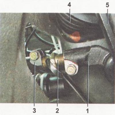
1 - tie rod end 2 - threaded insert; 3 - steering rod; 4 - telescopic stand; 5 - rotary lever
The steering knuckle is attached to the strut bracket with two bolts and nuts. The upper hole in the bracket is oval, and the bolt installed in it has an eccentric belt and an eccentric washer. When the upper bolt is turned, the steering knuckle moves along the radius, using the lower bolt as the axis of rotation. Due to this, the angle between the strut and the knuckle changes, which in turn allows you to adjust the camber of the front wheel on the car.
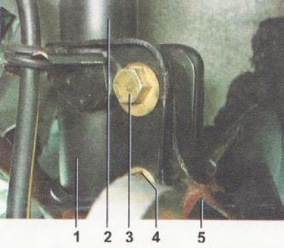
1 - steering knuckle mounting bracket; 2 - rack body; 3 - top (eccentric) steering knuckle mounting bolt; 4 - lower bolt of the steering knuckle mounting; 5 - steering knuckle
A double-row ball bearing is pressed into the hole of the steering knuckle and secured with two retaining rings. The wheel hub is pressed into the inner ring of the bearing.
At the bottom, the steering knuckle is connected to the transverse suspension arm using a ball joint. The transverse arm is held from moving by a brace, which is attached with its rear end through a silent block (rubber-metal hinge) to the lever, and the front ones - through the cushion to the crossbar. By changing the number of washers in the front and rear tie rod mounts, you can change the position of the lever, thereby adjusting the longitudinal tilt angle of the pivot axis.
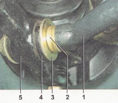
1 - rear end of longitudinal stretch; 2 - adjusting washers; 3 - thrust washer; 4 - silent block (rubber-metal hinge); 5 - Front suspension wishbone
The ends of the anti-roll bar are connected to the front suspension wishbones by means of struts. The central part of the anti-roll bar is secured to the body via rubber cushions. The movement of one of the arms is transmitted to the other via the anti-roll bar. This allows for partial synchronization of the operation of both sides of the suspension, thereby reducing vehicle sway on uneven roads and rolls in turns.
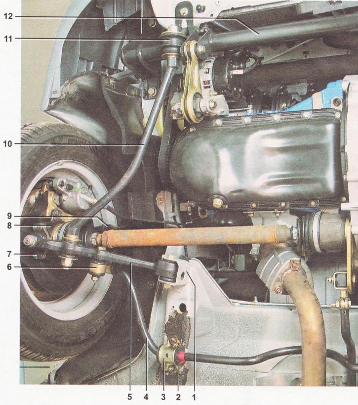
Front suspension design: 1 - transverse arm mounting bracket; 2 - stabilizer bar cushion; 3 - rod cushion bracket; 4 - stabilizer bar; 5 - transverse lever; 6 - stabilizer strut; 7 - ball joint; 8 - steering knuckle; 9 - telescopic stand; 10 - wishbone tensioner; 11 - Front mount bracket for wishbone brace; 12 - crossbar