

Circuit to test the switch
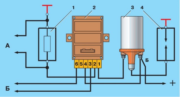
1 - resistor 0.01 Ohm±1%, not less than 20 W; 2 - switch; 3 - ignition coil; 4 – arrester; A - to the oscilloscope; B - to the generator of rectangular pulses
Waveform on the oscilloscope screen
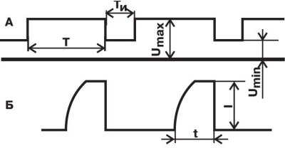
A - voltage pulses (U) generator;
B - current pulses (I) switch;
t is the current accumulation time;
T is the pulse period;
Ti - pulse duration
In a contactless ignition system, a switch type 3620.3734 or RT1903 or PZE4022 can be installed. It converts the control pulses of the proximity sensor into current pulses in the primary winding of the ignition coil.
The switch is checked using an oscilloscope and a square-wave generator according to the circuit in fig. Scheme for testing the switch. The output impedance of the generator should be 100-500 ohms. It is desirable to use a two-channel oscilloscope: the 1st channel is for generator pulses, and the 2nd channel is for switch pulses.
On terminals "3" And "6" The commutator receives square-wave pulses imitating sensor pulses. The pulse frequency is from 3.33 to 233 Hz, and the duty cycle (the ratio of the period to the pulse duration T / Ti is 3. The maximum voltage Umax is 10 V, and the minimum Umin is not more than 0.4 V (see waveform A in fig. Waveform on the oscilloscope screen). For a serviceable switch, the shape of the current pulses must correspond to waveform B (see fig. Waveform on the oscilloscope screen).
For switch 3620.3734 at supply voltage (13,5±0,5) V magnitude of current (I) should be 7.5–8.5 A. Current accumulation time (t) not standardized.
For the RT1903 switch, with the same supply voltage and frequency, the current strength is 7–8 A, and the accumulation time is 5.5–11.5 ms.
For switch PZE4022 with supply voltage (14±0,3) At and at a frequency of 25 Hz, the current strength is 7–9 A, and the current accumulation time is not standardized.
If the shape of the commutator pulses is distorted, then there may be interruptions in sparking or it may occur with a delay. The motor will overheat and not develop its rated power.
Attention! The plug connector must not be disconnected from the switch when the ignition is on, since in this case voltage up to 400 V may appear in certain sections of the switch circuit and it will be damaged.
Attention! It is not allowed to lay low voltage wires in the same bundle with high voltage wires.
Attention! It is not allowed to disconnect the wires from the battery terminals while the engine is running, as this may damage the switch.