
Scheme of the injection system
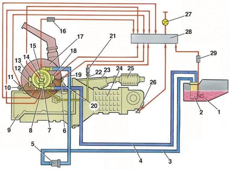
1 - fuel tank; 2 - electric fuel pump with fuel level sensor; 3 - supply line; 4 - drain line; 5 - fuel filter; 6 - inlet pipe with electric heater; 7 - pressure regulator; 8 – air temperature sensor; 9 - engine; 10 - outlet branch pipe of the cooling system; 11 - coolant temperature sensor; 12 - idle speed regulator; 13 - throttle drive sector; 14 - nozzle; 15 - central injection unit; 16 – the relay of a heater of an inlet pipe; 17 - air filter; 18 - throttle position sensor; 19 – oxygen concentration sensor; 20 - exhaust manifold; 21 - absolute pressure sensor; 22 - vacuum sampling tube; 23 - receiving pipe; 24 - gearbox; 25 - catalytic converter; 26 - speed sensor; 27 - control lamp "CHECK ENGINE"; 28 - electronic control unit; 29 - relay for turning on the electric fuel pump
Electronic control unit
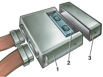
1 - electronic control unit; 2 - programmable read only memory (PROM); 3 - cover
Electronic control unit (ECU) 28 (see fig. Scheme of the injection system), located under the glove box, is the control center of the fuel injection system. It continuously processes information from various sensors and manages systems that affect exhaust emissions and vehicle performance. The control unit receives the following information:
- about the position and frequency of rotation of the crankshaft;
- about absolute air pressure;
- about air temperature;
- about the temperature of the coolant;
- about the position of the throttle;
- on the oxygen content in the exhaust gases;
- about the voltage in the on-board network of the car;
- about the speed of the car;
- about the request to turn on the air conditioner (if it is installed on the car);
- signal from the octane potentiometer.
Based on the information received, the unit controls the following systems and devices:
- fuel supply (nozzle and electric fuel pump);
- ignition system;
- idle control;
- electrically heated intake pipe;
- an adsorber of system of catching of vapors of gasoline;
- engine cooling fan;
- air conditioning compressor clutch (if it is on the car);
- diagnostic system.
The control unit turns on the output circuits (injector, various relays, etc.) by shorting them to ground through the output transistors of the control unit. The only exception is the fuel pump relay circuit. Only the winding of this relay is supplied by the ECU with 12 V.
The control unit has a built-in diagnostic system. It can recognize malfunctions in the system, warning the driver about them through a warning lamp "CHECK ENGINE". In addition, it stores diagnostic codes indicating fault areas to assist technicians in carrying out repairs.
Memory
There are two types of memory in the electronic control unit: random access memory (RAM) and one-time programmable read-only memory (PROM).
The working memory is "notebook" electronic control unit. The ECU microprocessor uses it to temporarily store measured parameters for calculations and for intermediate information. The microprocessor can enter data into it or read them out as necessary.
The RAM chip is mounted on the PCB of the ECU. This memory is volatile and requires an uninterruptible power supply to maintain. When the power supply is interrupted, the diagnostic trouble codes and calculated data contained in the RAM are erased.
Programmable Read Only Memory. The EPROM contains a common program that contains a sequence of working commands (control algorithms) and various calibration information. This information is control data for injection, ignition, idle, and the like. which depend on the mass of the car, the type and power of the engine, on the gear ratios of the transmission and other factors. PROM is also called a calibration memory.
The contents of the PROM cannot be changed after programming. This memory does not need power to save the information recorded in it, which is not erased when the power is turned off, i.e. this memory is non-volatile. The PROM is installed in a socket on the ECU board (see fig. Electronic control unit) and can be removed from the computer and replaced.
PROM individually for each vehicle configuration, although the same unified ECU can be used on different car models. Therefore, when replacing the PROM, it is important to set the correct model number and vehicle equipment. And when replacing a defective ECU, you can leave the old PROM (if it is correct).